|
|
| Ligne 9 : |
Ligne 9 : |
| | }} | | }} |
| | {{Introduction | | {{Introduction |
| − | |Introduction=<translate><u>'''Tools Required'''</u> | + | |Introduction=<translate>15/09/2025 |
| | | | |
| | | | |
| − | Standard screwdriver set
| + | Moved to Confluance |
| − |
| |
| − | Standard grease gun and cartridge
| |
| | | | |
| | | | |
| − | | + | Click [https://stuga-ltd.atlassian.net/wiki/external/YTRmMjYyZjA3MGVmNDYzMDk1ZDdlNTM0Y2VlMzk0Y2Q Here]</translate> |
| − | <u>'''Parts Required'''</u>
| |
| − | | |
| − | | |
| − | Mains air connection</translate>
| |
| | }} | | }} |
| | {{Materials}} | | {{Materials}} |
| | {{EPI}} | | {{EPI}} |
| | {{Tuto Step | | {{Tuto Step |
| − | |Step_Title=<translate>Caution</translate> | + | |Step_Title=<translate></translate> |
| − | |Step_Content=<translate>Output testing will be carried out under a no-emergency stop situation | + | |Step_Content=<translate></translate> |
| − | | |
| − | | |
| − | ensure pcl coupling is used for ability for quick disconnection
| |
| − | | |
| − | | |
| − | Ensure all colleagues are aware of testing and ensure good working practise is followed</translate>
| |
| − | |Step_Picture_00=R0015338_Bench_Assemble_Serial_Plate_caution.png
| |
| − | }}
| |
| − | {{Tuto Step
| |
| − | |Step_Title=<translate>Blank Spare ports</translate>
| |
| − | |Step_Content=<translate>Blank off all unused bulkhead and connection ports not required</translate>
| |
| − | |Step_Picture_00=R0015338_Bench_Assemble_Serial_Plate_caution.png
| |
| − | }}
| |
| − | {{Tuto Step
| |
| − | |Step_Title=<translate>Lubrication</translate>
| |
| − | |Step_Content=<translate>All lubrication points should be greased prior to testing
| |
| − | | |
| − | | |
| − | ensure the following are greased
| |
| − | | |
| − | | |
| − | '''<u>Leadscrews</u>'''
| |
| − | | |
| − | Z axis leadscrew 2off leadscrews 1 off grease point per leadscrew
| |
| − | | |
| − | Y Axis Leadscrew 1 off grease point
| |
| − | | |
| − | VZ axis leadscrew 1 off grease point
| |
| − | | |
| − | '''<u>Bearings</u>'''
| |
| − | | |
| − | 4 off Y axis bearings
| |
| − | | |
| − | 4 off Z axis bearings
| |
| − | | |
| − | 8 off VZ axis bearings
| |
| − | | |
| − | | |
| − | | |
| − | <br /></translate>
| |
| − | |Step_Picture_00=R0015320_Pneumatic_Output_Test_Screenshot_2023-11-06_113551.png
| |
| − | }}
| |
| − | {{Tuto Step
| |
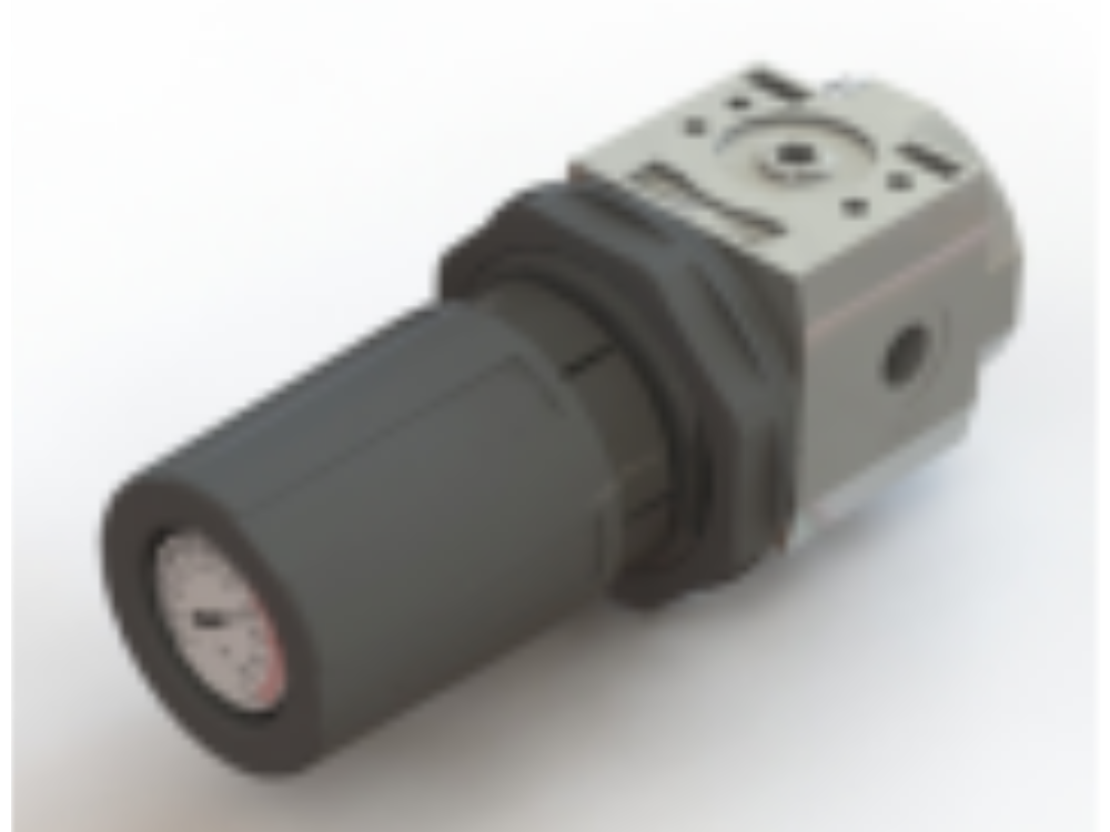
| − | |Step_Title=<translate>Connect air to Air service unit</translate>
| |
| − | |Step_Content=<translate>Ensure soft start adjuster is fully wound out
| |
| − | | |
| − | | |
| − | Set air service unit to 6 bar
| |
| − | | |
| − | <br /></translate>
| |
| − | |Step_Picture_00=R0015114_Bench_Assemble_Valve_Banks_and_Regulators_Screenshot_2023-11-02_073451.png
| |
| − | }}
| |
| − | {{Tuto Step
| |
| − | |Step_Title=<translate>Check Red Permanent feed line Air Gun</translate>
| |
| − | |Step_Content=<translate>Check for audible leaks and correct if required
| |
| − | | |
| − | | |
| − | Check operation of air gun . Ensure pressure is set to maximum of 2 bar</translate>
| |
| − | |Step_Picture_00=R0015338_Bench_Assemble_Serial_Plate_caution.png
| |
| − | }}
| |
| − | {{Tuto Step
| |
| − | |Step_Title=<translate>Check Red permanent feed Z axis</translate>
| |
| − | |Step_Content=<translate>Set Z axis support pressure. Set at 5 bar, and adjust to balance. Rotary ring should be held in position under cylinder pressure, but be able able to be moved up and down by turning the leadscrew by hand
| |
| − | | |
| − | If resistance is felt or axis bounces when leadscrew is turned , check air connections for correct piping</translate>
| |
| − | |Step_Picture_00=R0015114_Bench_Assemble_Valve_Banks_and_Regulators_Screenshot_2023-11-02_074048.png
| |
| − | }}
| |
| − | {{Tuto Step
| |
| − | |Step_Title=<translate>Check Red permanent feed VZ axis</translate>
| |
| − | |Step_Content=<translate>Set VZ axis regulator to 5 bar</translate>
| |
| − | |Step_Picture_00=R0015114_Bench_Assemble_Valve_Banks_and_Regulators_Screenshot_2023-11-02_074048.png
| |
| − | }}
| |
| − | {{Tuto Step
| |
| − | |Step_Title=<translate>Manual over Ride air service unit</translate>
| |
| − | |Step_Content=<translate>Manually override air service unit to purge Blue ring main
| |
| − | | |
| − | | |
| − | Caution All cylinders should move to their home positions
| |
| − | | |
| − | | |
| − | Check for audible leaks from ring main and cylinder connections
| |
| − | | |
| − | | |
| − | Check for leaks when all outputs are individually fire also</translate>
| |
| − | |Step_Picture_00=R0015338_Bench_Assemble_Serial_Plate_caution.png
| |
| − | }}
| |
| − | {{Tuto Step
| |
| − | |Step_Title=<translate>Test Y269 Ring blow</translate>
| |
| − | |Step_Content=<translate>Home position Blower should be switched off
| |
| − | | |
| − | | |
| − | Fire valve, blower should activate on tool break sensor assembly
| |
| − | | |
| − | | |
| − | Check orientation of in line flow regulator . Fully closed, air feed should stop totally . If not possible, flow regulator is fitted incorrectly</translate>
| |
| − | |Step_Picture_00=R0015320_Pneumatic_Output_Test_Screenshot_2023-11-02_085644.png
| |
| − | }}
| |
| − | {{Tuto Step
| |
| − | |Step_Title=<translate>Y270 Clamp hold</translate>
| |
| − | |Step_Content=<translate>Home position is retracted away from bottom rollers
| |
| − | | |
| − | | |
| − | Manually fire valve, cylinder should move toward datum rollers</translate>
| |
| − | |Step_Picture_00=R0015320_Pneumatic_Output_Test_Screenshot_2023-11-02_085644.png
| |
| − | }}
| |
| − | {{Tuto Step
| |
| − | |Step_Title=<translate>Y350 Infeed top clamp</translate>
| |
| − | |Step_Content=<translate>Home position should be lifted up
| |
| − | | |
| − | | |
| − | Manually fire valve, set regulator pressure to 2 bar
| |
| − | | |
| − | | |
| − | Clamp should move down when fired</translate>
| |
| − | |Step_Picture_00=R0015320_Pneumatic_Output_Test_Screenshot_2023-11-02_085644.png
| |
| − | }}
| |
| − | {{Tuto Step
| |
| − | |Step_Title=<translate>Y351 Infeed side clamp</translate>
| |
| − | |Step_Content=<translate>Home position should be retracted away from datum rollers
| |
| − | | |
| − | | |
| − | Manually fire valve, set regulator pressure to 2 bar
| |
| − | | |
| − | | |
| − | Clamp should move in when fired</translate>
| |
| − | |Step_Picture_00=R0015320_Pneumatic_Output_Test_Screenshot_2023-11-02_085644.png
| |
| − | }}
| |
| − | {{Tuto Step
| |
| − | |Step_Title=<translate>Y360 work blowers</translate>
| |
| − | |Step_Content=<translate>Home position Blower should be switched off
| |
| − | | |
| − | | |
| − | Fire valve, blower should activate on infeed datum roller assembly
| |
| − | | |
| − | | |
| − | Check orientation of in line flow regulator . Fully closed, air feed should stop totally . If not possible, flow regulator is fitted incorrectly</translate>
| |
| − | |Step_Picture_00=R0015320_Pneumatic_Output_Test_Screenshot_2023-11-02_085644.png
| |
| − | }}
| |
| − | {{Tuto Step
| |
| − | |Step_Title=<translate>Y386 Clamps middle</translate>
| |
| − | |Step_Content=<translate>Shared Output for top and side clamp
| |
| − | | |
| − | | |
| − | Home positions are
| |
| − | | |
| − | | |
| − | side clamp retracted away from datum rollers
| |
| − | | |
| − | Top clamp retracted away from datum rollers
| |
| − | | |
| − | | |
| − | Manually fire valve
| |
| − | | |
| − | | |
| − | Set
| |
| − | | |
| − | Y386 side clamp regulator to 2 bar
| |
| − | | |
| − | Y386 top clamp regulator to 2 bar
| |
| − | | |
| − | | |
| − | Clamps should move towards datum rollers
| |
| − |
| |
| − | Check that P0000160 flow regulators are orientated correctly. When fully wound in on adjustment, cylinder stroke should not be possible when the valve is manually fired. If flow regulation is not possible, orientation is incorrect
| |
| − | | |
| − | <br /></translate>
| |
| − | |Step_Picture_00=R0015320_Pneumatic_Output_Test_Screenshot_2023-11-02_085644.png
| |
| − | }}
| |
| − | {{Tuto Step
| |
| − | |Step_Title=<translate>V389 V Cut output</translate>
| |
| − | |Step_Content=<translate>Ensure all clamps are clear from V notch cut axis
| |
| − | | |
| − | | |
| − | Home position should be up
| |
| − | | |
| − | | |
| − | Manually fire valve
| |
| − | | |
| − | | |
| − | V notch assembly should move down towards the floor</translate>
| |
| − | |Step_Picture_00=R0015320_Pneumatic_Output_Test_Screenshot_2023-11-02_085644.png
| |
| − | }}
| |
| − | {{Tuto Step
| |
| − | |Step_Title=<translate>Y395 V clamp</translate>
| |
| − | |Step_Content=<translate>Y395 is a shared output for V top and side clamp
| |
| − | | |
| − | | |
| − | Home positions are
| |
| − | | |
| − | | |
| − | side clamp retracted away from datum rollers
| |
| − | | |
| − | Top clamp retracted away from datum rollers
| |
| − | | |
| − | | |
| − | Manually fire valve
| |
| − | | |
| − | | |
| − | Set
| |
| − | | |
| − | | |
| − | Y395 side clamp regulator to 4 bar
| |
| − | | |
| − | Y395 top clamp regulator to 4 bar
| |
| − | | |
| − | | |
| − | Clamps should move towards datum rollers when fired
| |
| − | | |
| − | Check that P0000160 flow regulators are orientated correctly. When fully wound in on adjustment, cylinder stroke should not be possible when the valve is manually fired. If flow regulation is not possible, orientation is incorrect</translate>
| |
| − | |Step_Picture_00=R0015320_Pneumatic_Output_Test_Screenshot_2023-11-02_085644.png
| |
| − | }}
| |
| − | {{Tuto Step
| |
| − | |Step_Title=<translate>Disconnect air</translate>
| |
| − | |Step_Content=<translate>Disconnect air and remove fitted blanks for testing</translate>
| |
| − | |Step_Picture_00=R0015114_Bench_Assemble_Valve_Banks_and_Regulators_Screenshot_2023-11-02_073451.png
| |
| | }} | | }} |
| | {{Notes}} | | {{Notes}} |

 Français
 English
 Deutsch
 Español
 Italiano
 Português