| [version en cours de rédaction] | [version en cours de rédaction] |
m (Gareth Green a déplacé la page R0015305 Install Wiring loom for Rotary Ring vers R0015305A Install Wiring loom for Rotary Ring : New revision ) |
|
(Aucune différence)
| |
Version actuelle datée du 24 septembre 2024 à 17:44
Installation of wiring loom and captivating spindle bases
Sommaire
- 1 Introduction
- 2 Étape 1 - Quality
- 3 Étape 2 - Quality Check
- 4 Étape 3 - Start Wiring loom installation
- 5 Étape 4 - Fit spindle plate 6
- 6 Étape 5 - Fit Spindle plate 5
- 7 Étape 6 - Fit Spindle plate 4
- 8 Étape 7 - Fit Spindle plate 3
- 9 Étape 8 - Fit Spindle plate 2
- 10 Étape 9 - Fit Spindle plate 1
- 11 Étape 10 - Fit Spindle plate 8
- 12 Étape 11 - Fit Spindle plate 7
- 13 Étape 12 - Fit dowels to spindle plates
- 14 Étape 13 - Add final fasteners
- 15 Étape 14 - Add anti drift marks
- 16 Étape 15 - Prepare back plates
- 17 Étape 16 - Fit back plate 1
- 18 Étape 17 - Fit back plate 2
- 19 Commentaires
Introduction
Tools Required
Standard hex key set
Ball pein hammer
6mm drift/punch
Drill driver
6mm hex drill attachment
Parts Required
D00000291 spindle plate x 8
M0000025 Ident numbers x 1
D0007703 r stop pin x 1
D0007990 cylinder anchor x 1
D0007777 Trunking backplate x 2Étape 1 - Quality
All bolts to have Loctite 243 adhesive applied unless otherwise stated
All bolts to be pen marked once adhesive applied and correct tension added
Étape 2 - Quality Check
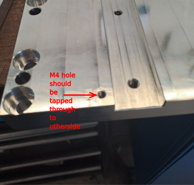
Check D0000291 spindle base has M4 hole tapped all the way through the plate. Rework if not
Étape 3 - Start Wiring loom installation
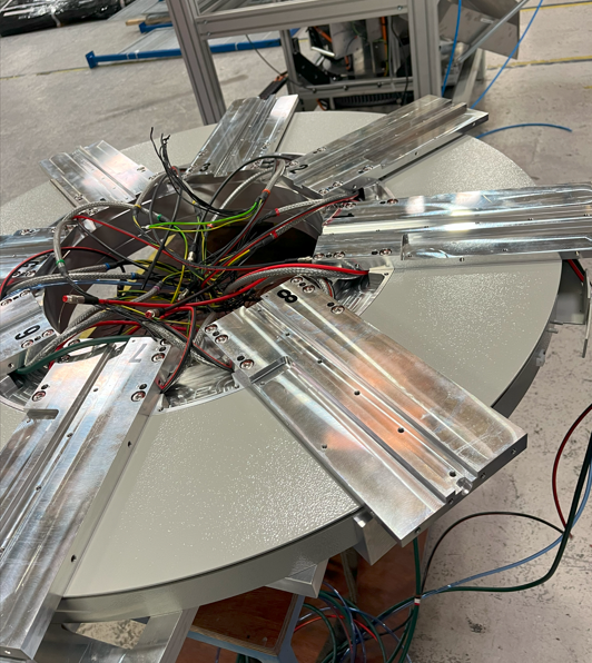
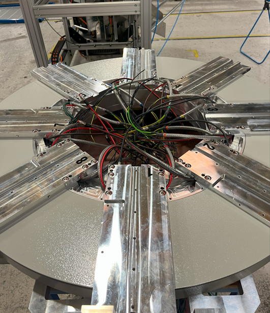
1 Segregate cables and 6mm blue pipe as shown
2 Use pre made cable identified as 6 and 7 and lay between 2 points shown
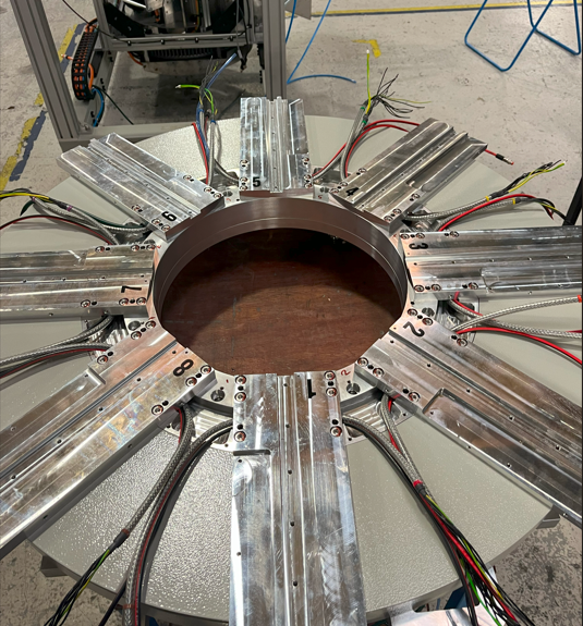
Étape 4 - Fit spindle plate 6
1 Fit D0000291 spindle plate and lightly secure with 2 off M8 x 25 socket caps in opposing corners
2 Fit M0000025 number ident (number 6)
Étape 5 - Fit Spindle plate 5
1 Retrieve pre marked ethercat cable marked SP5-SP6
2 Retrieve pre marked power cable marked 5-6
3 Lay both cables into chamber to the left of previous fitted plate
Ensure SP5 and 5 exit to left
Ensure SP6 and 6 exit to the right
4 Fit D0000291 spindle plate and lightly secure with 2 off M8 x 25 socket caps
5 Fit M0000025 ident number to spindle plate (number 5)
Étape 6 - Fit Spindle plate 4
1 Retrieve pre marked ethercat cable marked SP4-SP5
2 Retrieve pre marked power cable marked 4-5
3 Lay both cables into chamber to the left of previous fitted plate
Ensure SP4 and 4 exit to left
Ensure SP5 and 5 exit to the right
4 Fit D0000291 spindle plate and lightly secure with 2 off M8 x 25 socket caps
5 Fit M0000025 ident number to spindle plate (number 4)
Étape 7 - Fit Spindle plate 3
1 Retrieve pre marked ethercat cable marked SP3-SP4
2 Retrieve pre marked power cable marked 3-4
3 Lay both cables into chamber to the left of previous fitted plate
Ensure SP3 and 3 exit to left
Ensure SP4 and 4 exit to the right
4 Fit D0000291 spindle plate and lightly secure with 2 off M8 x 25 socket caps
5 Fit M0000025 ident number to spindle plate (number 3)
Étape 8 - Fit Spindle plate 2
1 Retrieve pre marked ethercat cable marked SP2-SP3
2 Retrieve pre marked power cable marked 2-3
3 Lay both cables into chamber to the left of previous fitted plate
Ensure SP2 and 2 exit to left
Ensure SP3 and 3 exit to the right
4 Fit D0000291 spindle plate and lightly secure with 2 off M8 x 25 socket caps
5 Fit M0000025 ident number to spindle plate (number 2)
Étape 9 - Fit Spindle plate 1
1 Retrieve pre marked ethercat cable marked SP1-SP2
2 Retrieve pre marked power cable marked 1-2
3 Lay both cables into chamber to the left of previous fitted plate
Ensure SP1 and 1 exit to left
Ensure SP2 and 2 exit to the right
4 Fit D0000291 spindle plate and lightly secure with 2 off M8 x 25 socket caps
5 Fit M0000025 ident number to spindle plate (number 1)
Étape 10 - Fit Spindle plate 8
1 Retrieve pre marked ethercat cable marked SP8-SP1
2 Retrieve pre marked power cable marked 8-1
3 Lay both cables into chamber to the left of previous fitted plate
Ensure SP8 and 8 exit to left
Ensure SP1 and 1 exit to the right
4 Fit D0000291 spindle plate and lightly secure with 2 off M8 x 25 socket caps
5 Fit M0000025 ident number to spindle plate (number 8)
Étape 11 - Fit Spindle plate 7
1 Retrieve pre marked ethercat cable marked SP7-SP8
2 Retrieve pre marked power cable marked 7-8
3 Lay both cables into chamber to the left of previous fitted plate
Ensure SP7 and 7 exit to left
Ensure SP8 and 8 exit to the right
4 Fit D0000291 spindle plate and lightly secure with 2 off M8 x 25 socket caps
5 Fit M0000025 ident number to spindle plate (number 7)
Étape 12 - Fit dowels to spindle plates
1 Ensure 2 off M8 x 25 sockets are only lightly tensioned. When fitting dowels spindle plates will need to move slightly to allow alignment to occur
2 Fit 4 off F0000042 8mm x 24mm dowel to each spindle plate. Start all 4 dowels into bores indicated , but do not drive flush
3 Use punch pin to drive dowels to approximately 10mm below spindle plate face
Étape 13 - Add final fasteners
1 Remove 2 off M8 x 25 socket cap fitted to each spindle plate
2 Fit 6 off M8 x 25 socket cap with adhesive to each spindle plate , do not wind bolt into thread
3 Use drill driver (torque setting 15) with 6mm hex attachment to drive all fasteners home
4 Finalise M8x25 socket caps by hand , and mark as completed
Étape 14 - Add anti drift marks
Each dowel hole (4 off per spindle plate, 32 in total) require anti drift dots adding to stop dowel slip in operation.
Use a centre punch and hammer, and add centre dot as indicated to slighty swage over top of dowel hole.
Repeat this for all dowel holes on spindle plates
Étape 15 - Prepare back plates
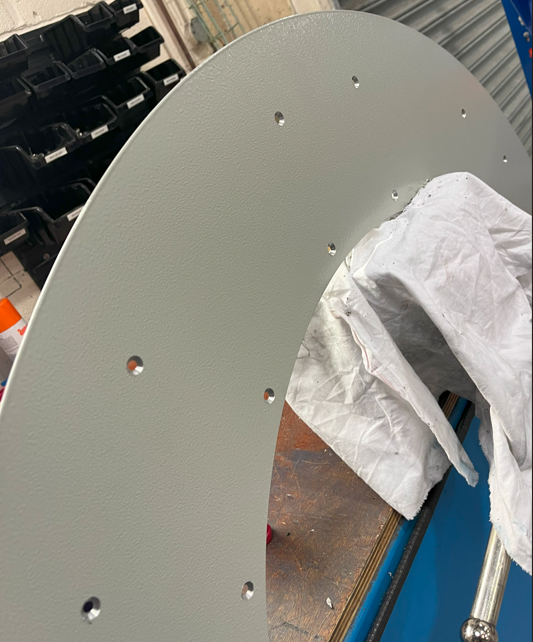
Prepare 2 off D0007777 trunking back plates for fitting
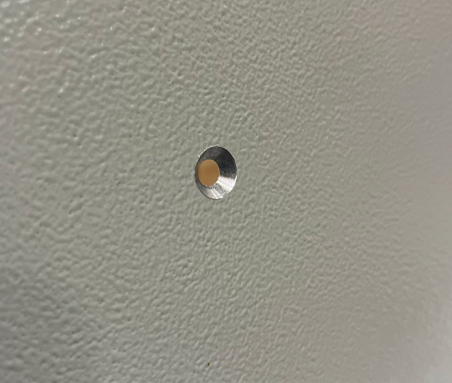
Check that a M5 countsunk bolt fits flush in all fixing holes.
If M5 countersunk sits above face, rework with Countersink to allow correct fitment
Étape 16 - Fit back plate 1
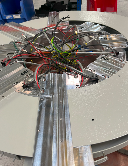
Trunking back plate 1 is positioned as shown
1 It should be fitted to the centre line of spindle plate 1 and 5, on the rear . (Picture shows fitted above for clarity of orientation only )
2 Slide back plate between spindle plates and lower trunking, and orientate as above.
3 Remove access cover to gain access to fit M5 x 10 countersunk bolts to fix backplate in position. Rotate ring to access all fastening points . 2 off fastening points will not be accessible at any point and are restricted by the energy chain mounting bracket and chain . These should be left unfixed at these points
Draft






 Français
 English
 Deutsch
 Español
 Italiano
 Português