| [version en cours de rédaction] | [version en cours de rédaction] |
(Page créée avec « {{Tuto Details |Main_Picture=R0000299_Stroke_assembly_rebuild_Part_2_2024-07-08_08-47-24.png |Main_Picture_annotation={"version":"2.4.6","objects":[{"type":"image","versio... ») |
|||
| Ligne 69 : | Ligne 69 : | ||
}} | }} | ||
{{Tuto Step | {{Tuto Step | ||
| − | |Step_Title=<translate>Check components</translate> | + | |Step_Title=<translate>Check components and fit</translate> |
|Step_Content=<translate>Ensure that keyway B0000041 passes through bevel gear D0007867. | |Step_Content=<translate>Ensure that keyway B0000041 passes through bevel gear D0007867. | ||
| Ligne 83 : | Ligne 83 : | ||
|Step_Picture_01=R0000299_Stroke_assembly_rebuild_Part_2_2024-07-08_08-50-09.png | |Step_Picture_01=R0000299_Stroke_assembly_rebuild_Part_2_2024-07-08_08-50-09.png | ||
|Step_Picture_02=R0000299_Stroke_assembly_rebuild_Part_2_2024-07-08_08-50-41.png | |Step_Picture_02=R0000299_Stroke_assembly_rebuild_Part_2_2024-07-08_08-50-41.png | ||
| + | }} | ||
| + | {{Tuto Step | ||
| + | |Step_Title=<translate>Mount spindle assembly</translate> | ||
| + | |Step_Content=<translate>Position spindle assembly to main gearbox body as shown. | ||
| + | |||
| + | |||
| + | Rotate spindle as shown to expose counterbored holes used for fixing | ||
| + | |||
| + | |||
| + | Fit 2 off M6x 50 socket caps and tension . Do not apply adhesive at this point</translate> | ||
| + | |Step_Picture_00=R0000299_Stroke_assembly_rebuild_Part_2_2024-07-08_08-59-06.png | ||
| + | }} | ||
| + | {{Tuto Step | ||
| + | |Step_Title=<translate>Check backlash</translate> | ||
| + | |Step_Content=<translate>Check backlash present by the following steps | ||
| + | |||
| + | |||
| + | 1 Insert 4mm key into fastener shown and use to stop rotation of vertical shaft | ||
| + | |||
| + | |||
| + | 2 Rock spindle clockwise and anti clockwise to gauge backlash present | ||
| + | |||
| + | |||
| + | Ideal backlash is 1mm movement in rotation of spindle (2)</translate> | ||
| + | |Step_Picture_00=R0000299_Stroke_assembly_rebuild_Part_2_2024-07-08_09-00-42.png | ||
| + | }} | ||
| + | {{Tuto Step | ||
| + | |Step_Title=<translate>Adjust backlash</translate> | ||
| + | |Step_Content=<translate>B</translate> | ||
}} | }} | ||
{{Notes}} | {{Notes}} | ||
{{PageLang | {{PageLang | ||
| + | |Language=en | ||
|SourceLanguage=none | |SourceLanguage=none | ||
|IsTranslation=0 | |IsTranslation=0 | ||
| − | |||
}} | }} | ||
{{Tuto Status | {{Tuto Status | ||
|Complete=Draft | |Complete=Draft | ||
}} | }} | ||
Version du 8 juillet 2024 à 10:03
Instructions for correct assembly and setting of stroke assembly gearboxes Original part numbers R0000728 and R0000729

Difficulté
Très difficile
Durée
1 minute(s)
Introduction
The following instructions should be followed to ensure that correct assembly and setting are performed
Tools / consumables Required
Standard hex key set
Standard spanner set
Large adjustable spanner
Drifts and punches
Ballpein hammer
Soft hammer
FE10 Solvent
Hylomar Gasket
Parts Required
Kit R0000299 containing
B0000043 Double Angular bearing 15 I?D 35 O?D 15.9 long rubber seal 3 x 2
B0000105 Double Angular Bearing 15 I/D 35 O/D 15.9 Long x 1
B0000335 3ph Brake motor 2 pole 3000rpm x 1
B0000380 Double Angular Bearing 25 I/D 52 O/D 20.6 Long + rubber seal x 2
D0000059 Damper Bridge x 1
D0000062 Damper Bridge Boss x 2
D0007730 ZX4 V Notch Mk1 Spindle Shaft x1
D0007867 Bevel Gear (Left) x 1
D0007868 Bevel Gear (Right ) x 1
D0007873 Motor Gear x 1
D0007874 Pinion Gear x 1
D0007875 Pinion Shaft x 1Étape 1 - Unless otherwise stated
Always use Loctite 243 on all fasteners fitted unless stated different
All bearings should be an acceptable fit, with Loctite 641 and FE10 solvent used if required
All fasteners should be marked once finalised

Étape 2 - Check components and fit
Ensure that keyway B0000041 passes through bevel gear D0007867.
Fit key to shaft
Fit Pinion gear to shaft
Secure with M5x16 socket cap and D0007721 washer. Do not use adhesive at this point . Do not fit shims at this point


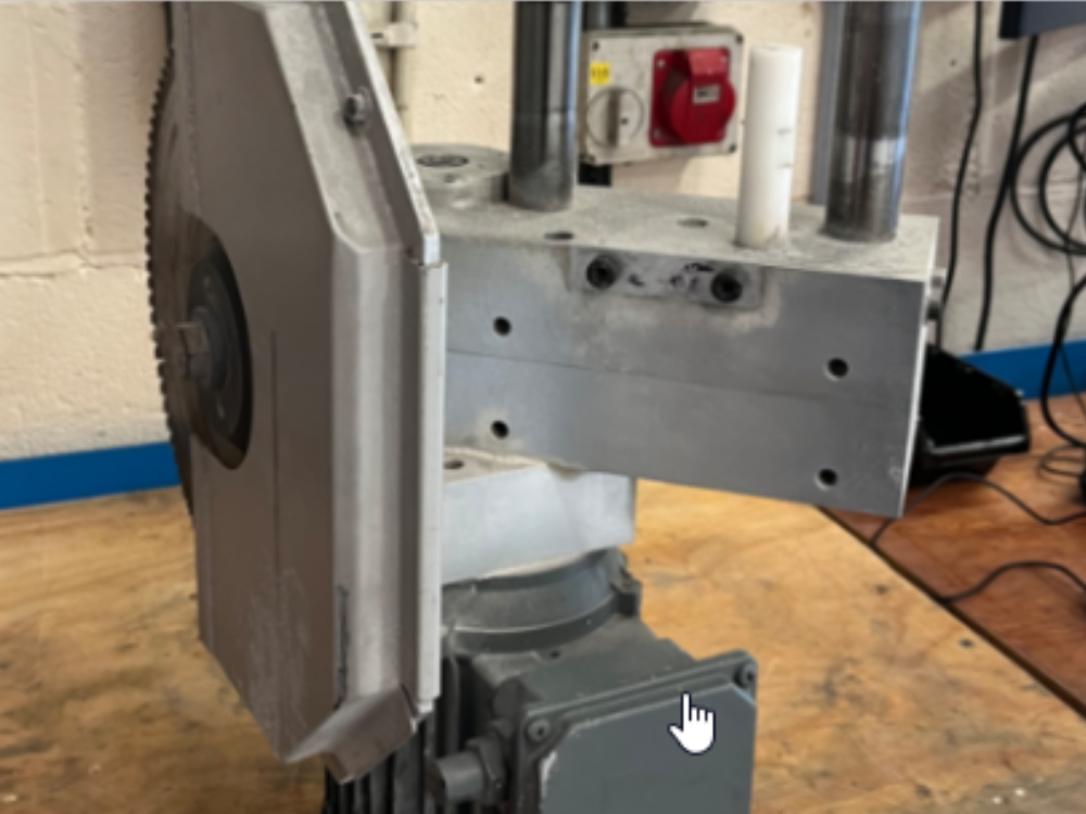
Étape 3 - Mount spindle assembly
Position spindle assembly to main gearbox body as shown.
Rotate spindle as shown to expose counterbored holes used for fixing
Fit 2 off M6x 50 socket caps and tension . Do not apply adhesive at this point

Étape 4 - Check backlash
Check backlash present by the following steps
1 Insert 4mm key into fastener shown and use to stop rotation of vertical shaft
2 Rock spindle clockwise and anti clockwise to gauge backlash present
Ideal backlash is 1mm movement in rotation of spindle (2)

Étape 5 - Adjust backlash
B
Draft
 Français
 English
 Deutsch
 Español
 Italiano
 Português