| [version en cours de rédaction] | [version en cours de rédaction] |
| Ligne 50 : | Ligne 50 : | ||
Pen mark all bolts to show finalised</translate> | Pen mark all bolts to show finalised</translate> | ||
|Step_Picture_00=R0015086_Assemble_Pneumatics_on_to_electrical_cabinet_loctite_243.png | |Step_Picture_00=R0015086_Assemble_Pneumatics_on_to_electrical_cabinet_loctite_243.png | ||
| + | }} | ||
| + | {{Tuto Step | ||
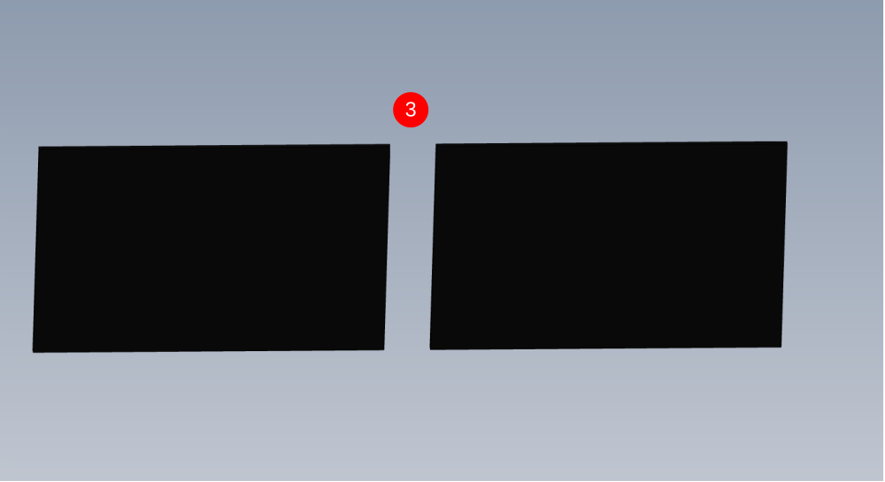
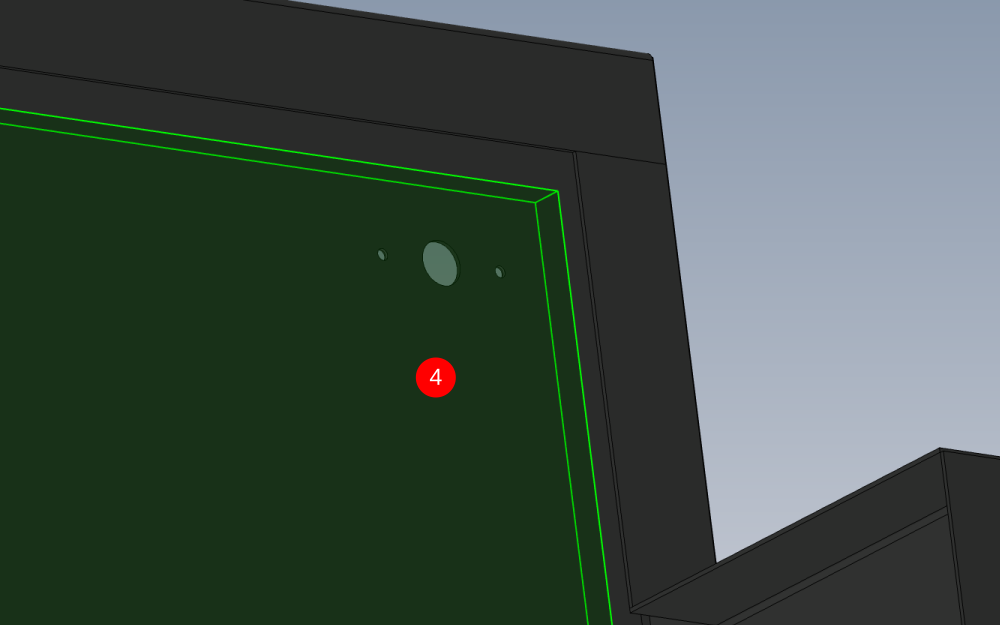
| + | |Step_Title=<translate>Quality Check</translate> | ||
| + | |Step_Content=<translate>Check fixing holes for printer assembly are in correct position as shown .</translate> | ||
| + | |Step_Picture_00=R0015290_Bench_Assemble_Top_guard_Screenshot_2024-01-29_115528.png | ||
| + | |Step_Picture_00_annotation={"version":"2.4.6","objects":[{"type":"image","version":"2.4.6","originX":"left","originY":"top","left":0,"top":0,"width":940,"height":693,"fill":"rgb(0,0,0)","stroke":null,"strokeWidth":0,"strokeDashArray":null,"strokeLineCap":"butt","strokeDashOffset":0,"strokeLineJoin":"miter","strokeMiterLimit":4,"scaleX":0.64,"scaleY":0.64,"angle":0,"flipX":false,"flipY":false,"opacity":1,"shadow":null,"visible":true,"clipTo":null,"backgroundColor":"","fillRule":"nonzero","paintFirst":"fill","globalCompositeOperation":"source-over","transformMatrix":null,"skewX":0,"skewY":0,"crossOrigin":"","cropX":0,"cropY":0,"src":"https://stuga.dokit.app/images/9/96/R0015290_Bench_Assemble_Top_guard_Screenshot_2024-01-29_115528.png","filters":[]},{"type":"wfellipse","version":"2.4.6","originX":"center","originY":"center","left":269.19,"top":123.81,"width":53.01,"height":53.01,"fill":"rgba(255,0,0,0)","stroke":"#FF0000","strokeWidth":2,"strokeDashArray":null,"strokeLineCap":"butt","strokeDashOffset":0,"strokeLineJoin":"miter","strokeMiterLimit":4,"scaleX":1,"scaleY":1,"angle":0,"flipX":false,"flipY":false,"opacity":1,"shadow":null,"visible":true,"clipTo":null,"backgroundColor":"","fillRule":"nonzero","paintFirst":"fill","globalCompositeOperation":"source-over","transformMatrix":null,"skewX":0,"skewY":0,"rx":26.503465735050014,"ry":26.503465735050014},{"type":"wfellipse","version":"2.4.6","originX":"center","originY":"center","left":460,"top":241,"width":200,"height":200,"fill":"rgba(255,0,0,0)","stroke":"#FF0000","strokeWidth":2,"strokeDashArray":null,"strokeLineCap":"butt","strokeDashOffset":0,"strokeLineJoin":"miter","strokeMiterLimit":4,"scaleX":1,"scaleY":1,"angle":0,"flipX":false,"flipY":false,"opacity":1,"shadow":null,"visible":true,"clipTo":null,"backgroundColor":"","fillRule":"nonzero","paintFirst":"fill","globalCompositeOperation":"source-over","transformMatrix":null,"skewX":0,"skewY":0,"rx":100,"ry":100}],"height":442,"width":600} | ||
}} | }} | ||
{{Tuto Step | {{Tuto Step | ||
Version actuelle datée du 29 janvier 2024 à 13:56
Assembly instructions

Difficulté
Moyen
Durée
1.5 heure(s)
Introduction
Tools Required
Standard hex key set
Acoustic foam cutting edge and Back board
Stanley blade
Standard HSS drill set
Standard tap set
Step drill
Parts Required
D0001352 Printer Shelf TLP2844-Z x 1
D0004719E Cut Bar Guard Mk5 (5476E) x 1
E0000249 Sounder Beacon x 1
M0000002 12mm Grey Acoustic Foam with Black PVC Facing x 1
M0001127 Cable Tie Base (m6) x 1
Étape 1 - Unless otherwise stated
Use loctite 243 on all fasteners
Use Loctite 572 on all threaded pneumatic connections
Pen mark all bolts to show finalised

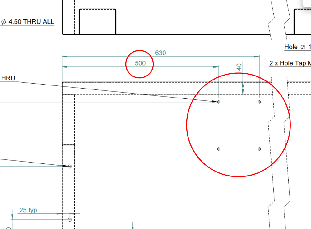
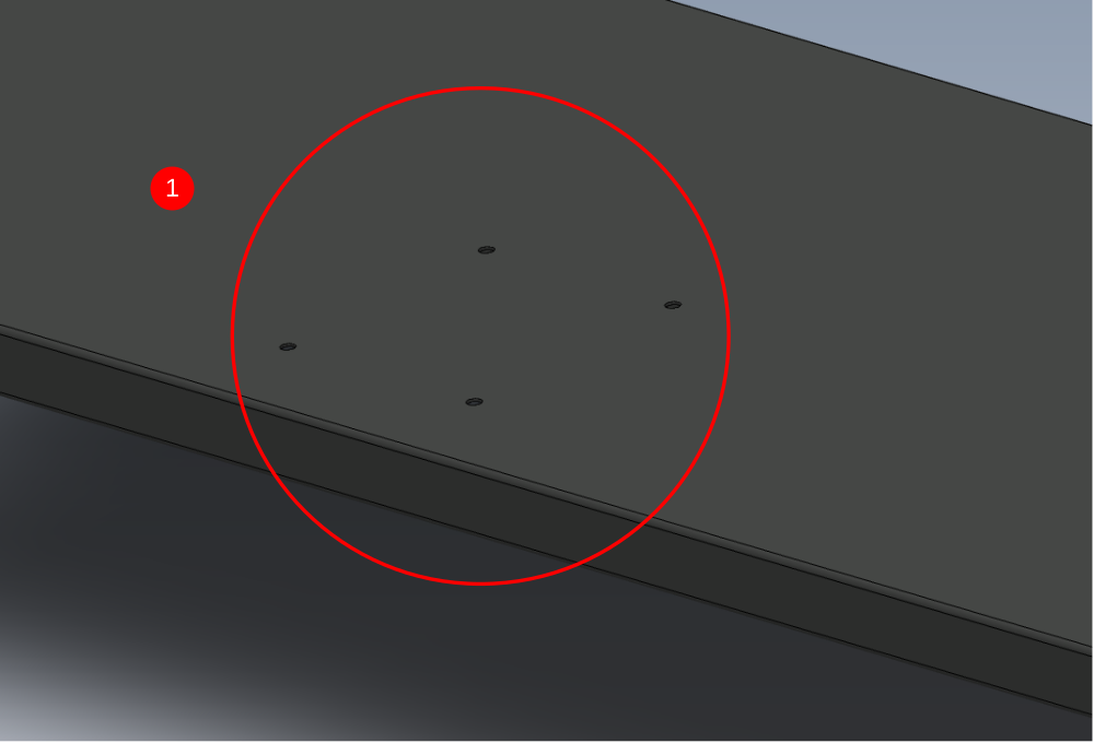
Étape 2 - Quality Check
Check fixing holes for printer assembly are in correct position as shown .
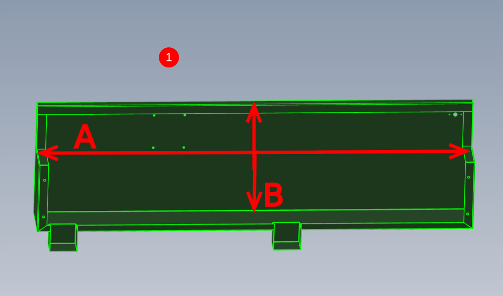
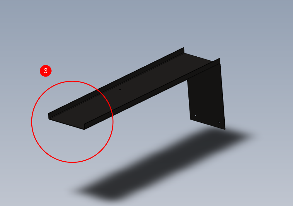
Étape 3 - Acoustic sound proof fitting
1 Measure internal dimensions of cut guard as shown
Reduce measurement A by 5mm
Reduce measurement B by 35mm
Guide measurements 1845mm x 465mm
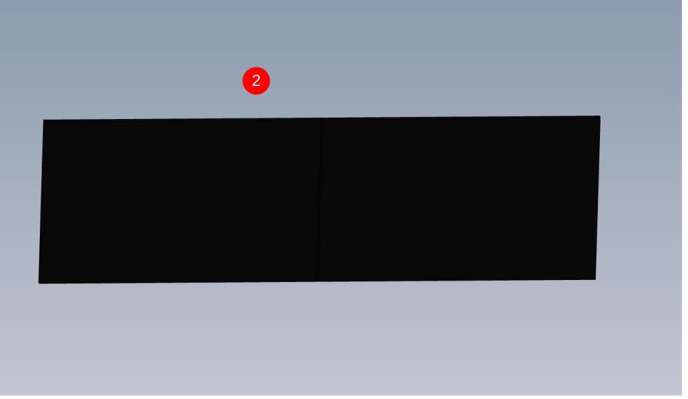
2 Cut a section of M0000002 acoustic foam to these measurements , ensuring squareness and parallel. Use cutting board, straight edge and sharp stanley blade
3 Once cut,measure and cut to divide the piece into equal sections as shown
4 Offer up first section of acoustic foam as shown , and mark position of 3 indicated holes thpugh onto the acoustic foam
5 Mark a 75mm x 50mm rectangle to be equal around the marked area on the acoustic foam
6 Cut out this section, then remove adhesive backing cover and fix acoustic foam in place
7 FFit 2nd section of acoustic foam to align with first
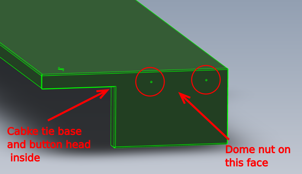
Étape 4 - Attach cable bases
1 Attach 2 off M4 cable bases to the indicated holes. The tie bases should sit internally and are fixed with M4 x 6 button heads and finished with a M4 dome nut on the outside face
2 Loop 2 off white tie wraps through fitted bases and lock to first tab (ready for cables to be fed later )
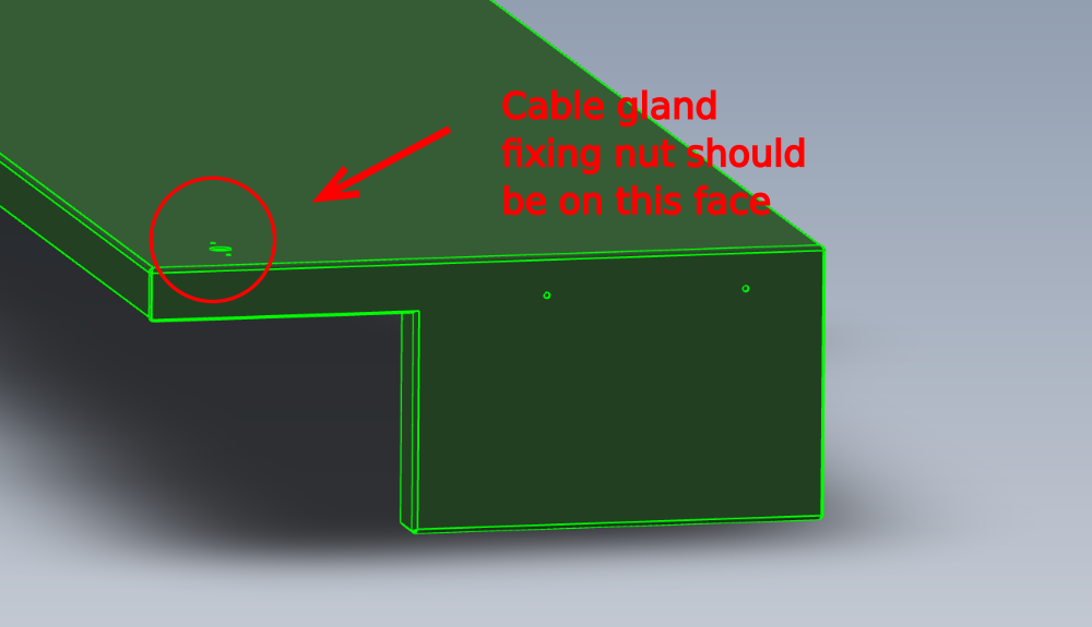
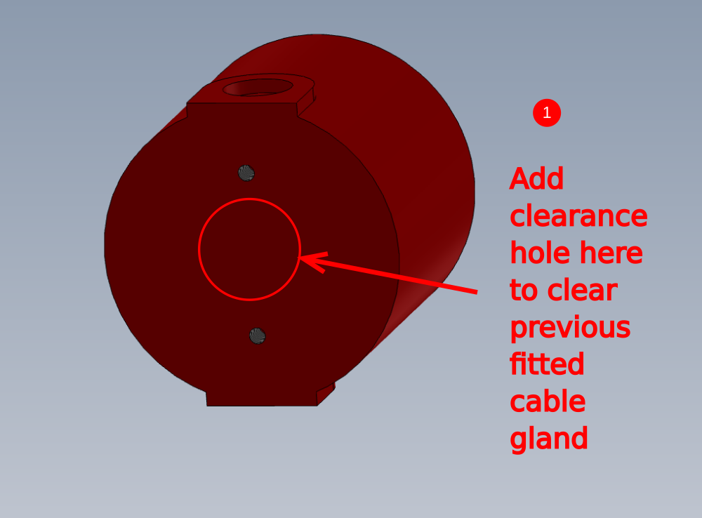
Étape 5 - Fit cable gland
Fit cable gland and nut
( part numbers required)
to indicated hole. Gland should be fitted so the fixing nut is on the indicated face
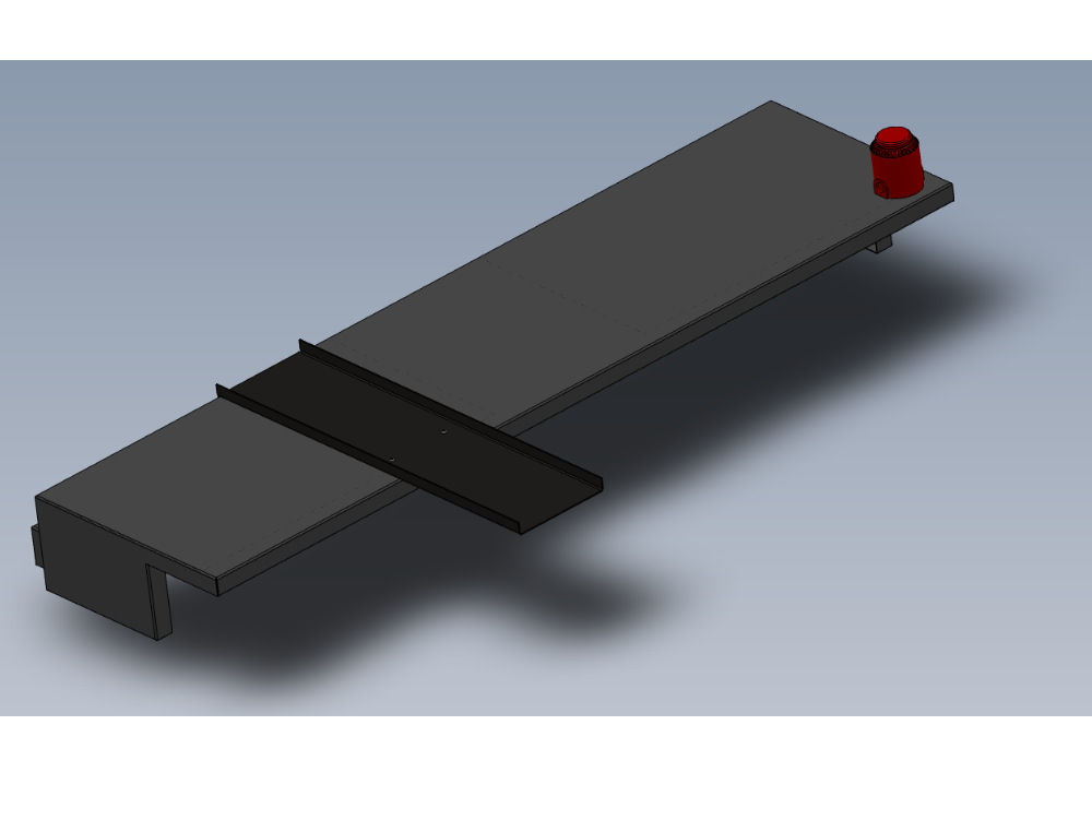
Étape 6 - Fit Sounder beacon
1 E0000249 Sounder Beacon will need adjusting to accept cable gland when fitted . Use step drill to add a hole to the base of the beacon to allow clearance for the cable gland nut when fitted (size of hole required )
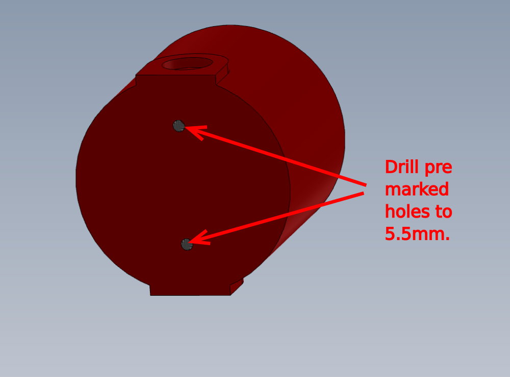
2 Offer beacon up to cut guard and identify the 2 holes that required drilling in the beacon to allow fixing. Drill these to 5.5mm
3 Secure beacon the cut guard using M5 x 12 socket caps and a form washers
4 Using masking tape to secure top section of sounder beacon along side fitted base
Étape 7 - Fit Printer tray
1 Use 8mm hss drill through indicated holes to clear acustic foam ready for fixings
2 Attach D0001352 Printer Shelf TLP2844-Z as shown using 4 off M8 x 30 button sockets (check size) , and add heavy M8 washer and M8 nylocs to acoustic foam side
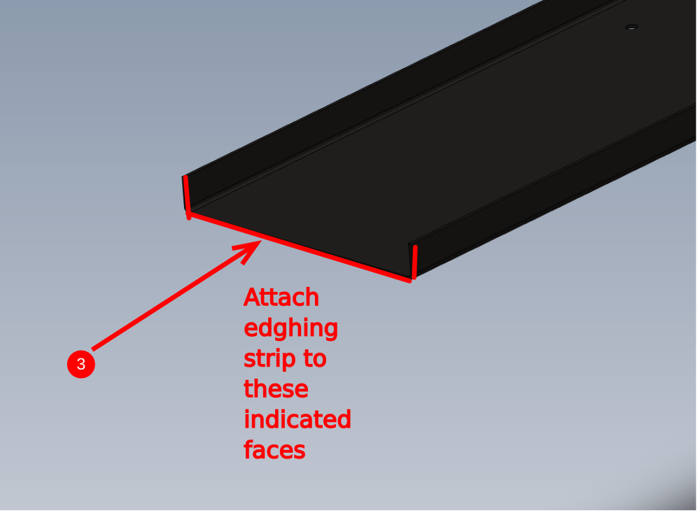
3 Attach M0000031 (from consumable stock) to indicated faces of printer tray

Draft
 Français
 English
 Deutsch
 Español
 Italiano
 Português