| [version en cours de rédaction] | [version en cours de rédaction] |
(Page créée avec « {{Tuto Details |Main_Picture=ZX5_Production_R0015040_Module_F_to_R0015001B_Module_E_alignment_Screenshot_2023-12-08_135219.png |Main_Picture_annotation={"version":"2.4.6",... ») |
|||
| Ligne 14 : | Ligne 14 : | ||
{{EPI}} | {{EPI}} | ||
{{Tuto Step | {{Tuto Step | ||
| − | |Step_Title=<translate></translate> | + | |Step_Title=<translate>Position Module F</translate> |
| − | |Step_Content=<translate></translate> | + | |Step_Content=<translate>Position module F at end of Module E infeed frame |
| + | |||
| + | Approximately Align Saw roller back fences to Saw infeed back fences | ||
| + | |||
| + | Approximately align X axis position by setting the to frames spaced at the distance shown of 20mm</translate> | ||
| + | |Step_Picture_00=ZX5_Production_R0015040_Module_F_to_R0015001B_Module_E_alignment_Screenshot_2023-12-20_132625.png | ||
| + | |Step_Picture_01=ZX5_Production_R0015040_Module_F_to_R0015001B_Module_E_alignment_Screenshot_2023-12-20_132631.png | ||
| + | }} | ||
| + | {{Tuto Step | ||
| + | |Step_Title=<translate>Level Module F</translate> | ||
| + | |Step_Content=<translate>Use the indicated points to level the frame. | ||
| + | |||
| + | Use cut table indicated as levelling point | ||
| + | |||
| + | Level Y and X Axis of saw | ||
| + | |||
| + | # | ||
| + | #</translate> | ||
| + | |Step_Picture_00=ZX5_Production_R0015040_Module_F_to_R0015001B_Module_E_alignment_Screenshot_2023-12-20_132716.png | ||
| + | |Step_Picture_01=ZX5_Production_R0015040_Module_F_to_R0015001B_Module_E_alignment_Screenshot_2023-12-20_132722.png | ||
| + | }} | ||
| + | {{Tuto Step | ||
| + | |Step_Title=<translate>Quality check</translate> | ||
| + | |Step_Content=<translate>It is vital to confirm Cut tables are in the correct position once levelled, and that movement has occurred during transport | ||
| + | |||
| + | To do this the base of the saw turn table must be checked for level. These readings must read exactly the same as the levelled cut table in the previous step | ||
| + | |||
| + | Any discrepancy should be reported</translate> | ||
| + | |Step_Picture_00=ZX5_Production_R0015040_Module_F_to_R0015001B_Module_E_alignment_Screenshot_2023-12-20_132804.png | ||
| + | |Step_Picture_01=ZX5_Production_R0015040_Module_F_to_R0015001B_Module_E_alignment_Screenshot_2023-12-20_132815.png | ||
| + | }} | ||
| + | {{Tuto Step | ||
| + | |Step_Title=<translate>Saw Height Adjustment</translate> | ||
| + | |Step_Content=<translate>Saw module should be raised or lowered to align with blue load rollers on saw infeed table | ||
| + | |||
| + | Saw module should sit above blue rollers by no more than 1mm | ||
| + | |||
| + | Ensure levels previously set are not compromised when adjusting height | ||
| + | |||
| + | Double check levels are still correct once height has been adjusted</translate> | ||
| + | |Step_Picture_00=ZX5_Production_R0015040_Module_F_to_R0015001B_Module_E_alignment_Screenshot_2023-12-20_132854.png | ||
| + | }} | ||
| + | {{Tuto Step | ||
| + | |Step_Title=<translate>Laser alignment of Saw to Saw infeed height</translate> | ||
| + | |Step_Content=<translate>1 Position base of laser against back fence rollers and cast beam towards gripper | ||
| + | |||
| + | 2 Position Gripper directly Infront of laser and mark vertical line on gripper to match laser dot | ||
| + | |||
| + | 3 Rotate laser so base is on cut table and mark a horizontal line on the gripper to match the laser dot | ||
| + | |||
| + | 3 Move Gripper to point one indicated , and inspect horizontal line to laser dot . Any discrepancy can be adjusted by the 2 off adjusting floor bolts directly below | ||
| + | |||
| + | 4 Repeat this step and indicated points 2,3 and 4</translate> | ||
| + | |Step_Picture_00=ZX5_Production_R0015040_Module_F_to_R0015001B_Module_E_alignment_Screenshot_2023-12-20_132931.png | ||
| + | |Step_Picture_01=ZX5_Production_R0015040_Module_F_to_R0015001B_Module_E_alignment_Screenshot_2023-12-20_132942.png | ||
| + | }} | ||
| + | {{Tuto Step | ||
| + | |Step_Title=<translate>Adjust alignment Saw module</translate> | ||
| + | |Step_Content=<translate>Rotate the laser so the base is against the rear roller fence, and ensure the gripper is at its furthest point of travel away from the saw . Project the laser to the gripper. Adjust Saw module in directions shown to align the laser to the vertical mark on gripper</translate> | ||
| + | |Step_Picture_00=ZX5_Production_R0015040_Module_F_to_R0015001B_Module_E_alignment_Screenshot_2023-12-20_133021.png | ||
| + | }} | ||
| + | {{Tuto Step | ||
| + | |Step_Title=<translate>Check laser alignment</translate> | ||
| + | |Step_Content=<translate>With the laser still casting along the infeed table, slowly return the gripper along the axis and inspect the laser dot in relation to lines added to gripper. Discrepancy should be less than 4mm on both axis</translate> | ||
| + | |Step_Picture_00=R0008013_Clacker_assembly_quality.png | ||
}} | }} | ||
{{Notes}} | {{Notes}} | ||
{{PageLang | {{PageLang | ||
| + | |Language=en | ||
|SourceLanguage=none | |SourceLanguage=none | ||
|IsTranslation=0 | |IsTranslation=0 | ||
| − | |||
}} | }} | ||
{{Tuto Status | {{Tuto Status | ||
|Complete=Draft | |Complete=Draft | ||
}} | }} | ||
Version du 20 décembre 2023 à 15:31
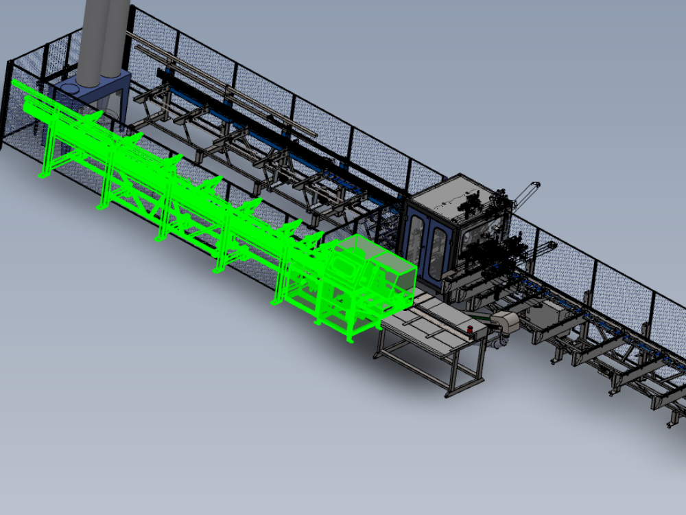
Details for correct alignment and process steps

Difficulté
Difficile
Durée
2 heure(s)
Introduction
Alignment criteria and steps for correct machine installation
Étape 1 - Position Module F
Position module F at end of Module E infeed frame
Approximately Align Saw roller back fences to Saw infeed back fences
Approximately align X axis position by setting the to frames spaced at the distance shown of 20mm


Étape 2 - Level Module F
Use the indicated points to level the frame.
Use cut table indicated as levelling point
Level Y and X Axis of saw


Étape 3 - Quality check
It is vital to confirm Cut tables are in the correct position once levelled, and that movement has occurred during transport
To do this the base of the saw turn table must be checked for level. These readings must read exactly the same as the levelled cut table in the previous step
Any discrepancy should be reported


Étape 4 - Saw Height Adjustment
Saw module should be raised or lowered to align with blue load rollers on saw infeed table
Saw module should sit above blue rollers by no more than 1mm
Ensure levels previously set are not compromised when adjusting height
Double check levels are still correct once height has been adjusted

Étape 5 - Laser alignment of Saw to Saw infeed height
1 Position base of laser against back fence rollers and cast beam towards gripper
2 Position Gripper directly Infront of laser and mark vertical line on gripper to match laser dot
3 Rotate laser so base is on cut table and mark a horizontal line on the gripper to match the laser dot
3 Move Gripper to point one indicated , and inspect horizontal line to laser dot . Any discrepancy can be adjusted by the 2 off adjusting floor bolts directly below
4 Repeat this step and indicated points 2,3 and 4


Étape 6 - Adjust alignment Saw module
Rotate the laser so the base is against the rear roller fence, and ensure the gripper is at its furthest point of travel away from the saw . Project the laser to the gripper. Adjust Saw module in directions shown to align the laser to the vertical mark on gripper

Étape 7 - Check laser alignment
With the laser still casting along the infeed table, slowly return the gripper along the axis and inspect the laser dot in relation to lines added to gripper. Discrepancy should be less than 4mm on both axis

Draft
 Français
 English
 Deutsch
 Español
 Italiano
 Português