| [version en cours de rédaction] | [version en cours de rédaction] |
| Ligne 149 : | Ligne 149 : | ||
}} | }} | ||
{{Tuto Step | {{Tuto Step | ||
| − | |Step_Title=<translate>Remove | + | |Step_Title=<translate>Remove pcl connections</translate> |
|Step_Content=<translate>once testing is complete remove air coupling and associated cable/pipe management installed for testing</translate> | |Step_Content=<translate>once testing is complete remove air coupling and associated cable/pipe management installed for testing</translate> | ||
}} | }} | ||
Version du 14 juillet 2023 à 14:48
Instructions to pneumatically test build module

Difficulté
Moyen
Durée
2 heure(s)
Sommaire
- 1 Introduction
- 2 Étape 1 - Health and Safety
- 3 Étape 2 - Check all connections are made
- 4 Étape 3 - Connect air feed
- 5 Étape 4 - check for air leaks
- 6 Étape 5 - Check home positions
- 7 Étape 6 - Test valve bank outputs
- 8 Étape 7 - Test Y244 material load sensor blowers should be switched OFF
- 9 Étape 8 - Test Y125 Pop up C should be retracted
- 10 Étape 9 - Test Y124 Roller beds should be lifted
- 11 Étape 10 - Test Y126/Y127 Beam position
- 12 Étape 11 - Test Y122 Rack blower
- 13 Étape 12 - Y121 Gripper height
- 14 Étape 13 - Remove pcl connections
- 15 Commentaires
Introduction
Tools required
Pcl air line -12mm connector
Parts Required
Étape 1 - Health and Safety
In this process pneumatic outputs will be tested in a non emergency stop environment
Ensure safe working practice is followed
- Ensure Machine test area is clear from personnel and all staff are aware of testing procedure commencing
- Ensure all Air connection lines are connected
- Ensure all walkways are not impeded by trailing pipes/leads
- Ensure all mechanical assemblies are at a sufficient stage for testing

Étape 2 - Check all connections are made
- Check all valve bank ports are either connected or blanked off
- Check all mains feed pipes are connected or isolated
- Check all regulators are regulated to minimum setting
- Check all air flow control valves on cylinders and blow lines are set to mid range adjustment
Étape 3 - Connect air feed
Connect air feed to mains 12mm feed pipe using pcl coupling and 12mmm push fit adapter
Étape 4 - check for air leaks
Investigate any air leaks and resolve
Étape 5 - Check home positions
With no valves active ( no over rides pressed ) the following home positions of pneumatic assemblies should be
1 Y244 material load sensor blowers should be switched OFF
2 Y125 Pop up C should be retracted
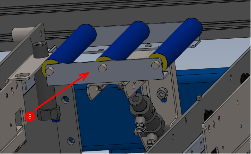
3 Y124 Roller beds should be lifted
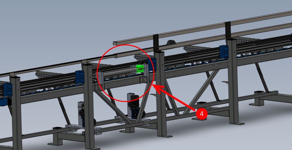
4 Y126/Y127 Beam position should be closest to extraction end
5 Y122 Rack blower ashould be switched OFF
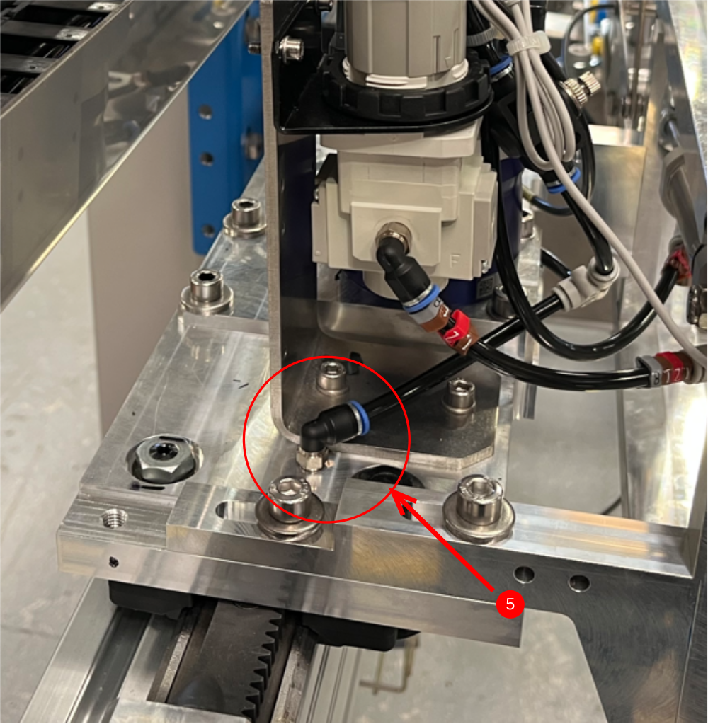
6 Y121 Gripper height should be raised up
Any discrepancies on these should be investigated to correct
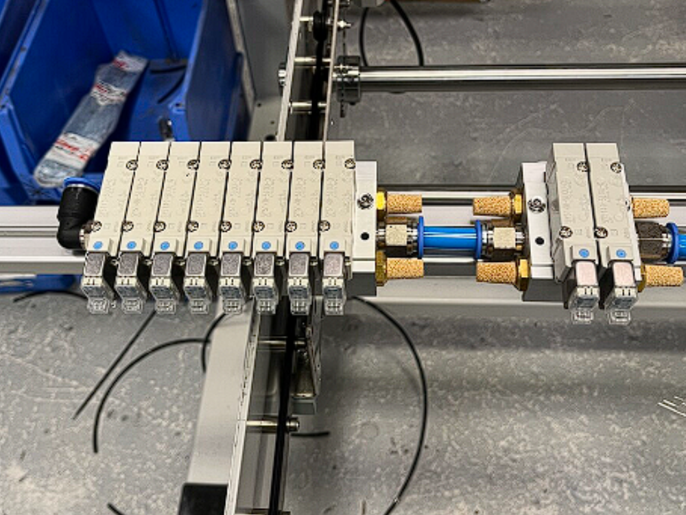
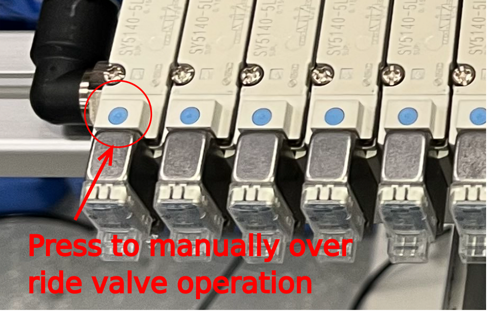
Étape 6 - Test valve bank outputs
Each valve on the Valve bank can be manually overridden to activate the output.
When each valve is fired, attention should be paid to identify any air leaks that occur when the active side of the system becomes live
Étape 7 - Test Y244 material load sensor blowers should be switched OFF
manually fire Y244 .
Check that flow regulator is fitted in the correct orientation . Check this by holding the valve on over ride then adjusti the thumb wheel fully clockwise until the air flow stops , then turn fully anti clockwise and air flow should reach maximum
It no adjustment is possible from thumb wheel, this means the flow regulator is fitted back to front
Étape 8 - Test Y125 Pop up C should be retracted
Manually overiding Y125 valve should make All pop up cylinders fire the piston into the active position
Check for air leaks in active position
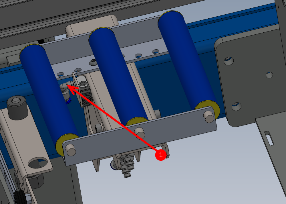
Étape 9 - Test Y124 Roller beds should be lifted
Manually over ride Y124 and all roller beds should drop down from the lifted position. Investigate any air leaks in the activated position
Movement should be smooth , and even across all roller beds operating.
If movement is violent, check that process has been followed and all flow regs are set to 2 1/2 turns open from the fully closed position.
Report through ncr if this is the case
Étape 10 - Test Y126/Y127 Beam position
Manually override Y126/Y127 valve to move hepco drive beam into the active forward position
Investigate any air leaks when active
Étape 11 - Test Y122 Rack blower
manually fire Y122.
Check that flow regulator is fitted in the correct orientation . Check this by holding the valve on over ride then adjusti the thumb wheel fully clockwise until the air flow stops , then turn fully anti clockwise and air flow should reach maximum
It no adjustment is possible from thumb wheel, this means the flow regulator is fitted back to front
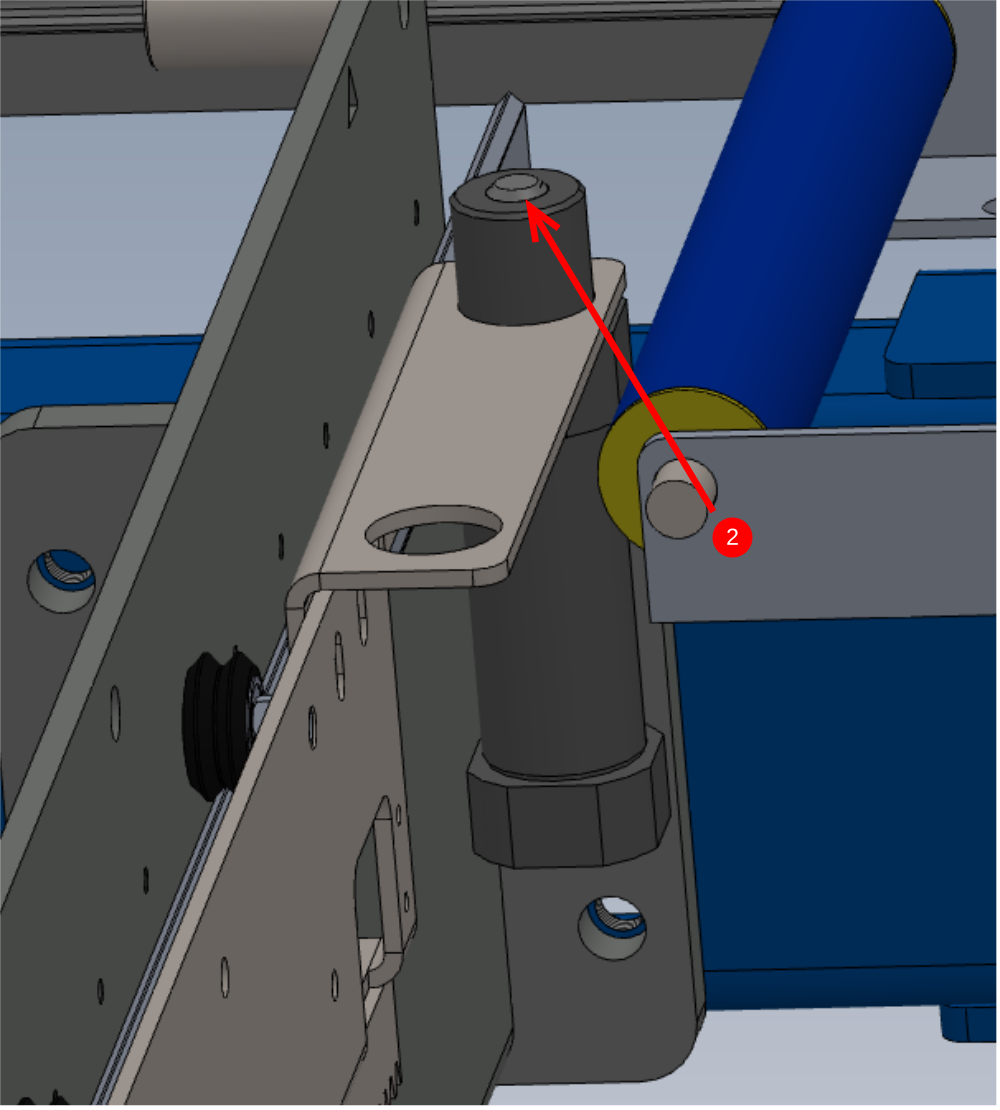
Étape 12 - Y121 Gripper height
Manually fire Y121
With valve held in the over ridden state, adjust regulator next to gripper to increase pressure to 0.4 MPA and then reduce pressure to zero. This is to confirm regulator is fitted to the system correctly . If regulation is not possible, check piping as fault is evident .
Once happy with operation, set regulator pressure to 0.15 MPA
Étape 13 - Remove pcl connections
once testing is complete remove air coupling and associated cable/pipe management installed for testing
Draft
 Français
 English
 Deutsch
 Español
 Italiano
 Português