| [version en cours de rédaction] | [version en cours de rédaction] |
m (Gareth Green a déplacé la page R0015094 Set drive pinions in position vers R0015249 Set drive pinions in position) |
|
(Aucune différence)
| |
Version du 23 juin 2023 à 13:31
Instructions to correctly set drive pinions into positions on shafts

Difficulté
Moyen
Durée
1 heure(s)
Introduction
Tools Required
Standard Hex key set
Parts Required
Étape 1 - Unless otherwise stated
Use Loctite 243 on all fasteners
Use Loctite 572 on all threaded pneumatic connections
Pen mark all fasteners to show finalised

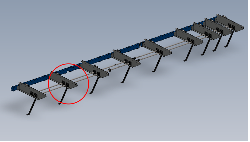
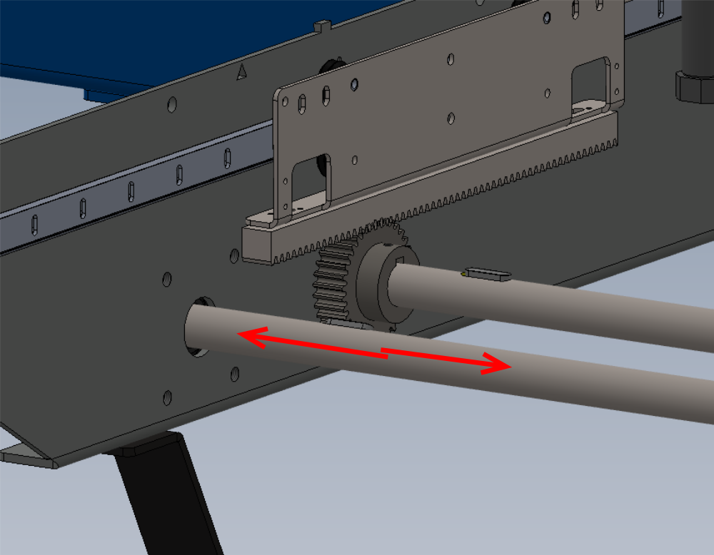
Étape 2 - Set shaft position
- Each pair of shafts that are joined together can be moved in the directions show to give the optimal contact on keys and drive pinions
- Take all 9 arm positions into consideration and position each shaft accordingly to achieve the best overall position to suit all arms
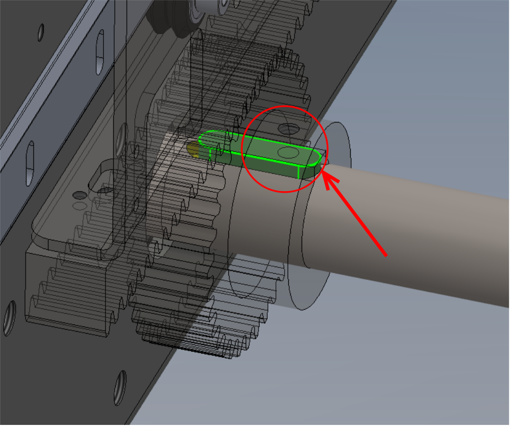
- Pinion lock points should always be above keyways
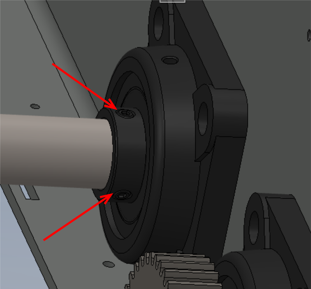
Étape 3 - Lock shaft position
Individually remove and apply Loctite 243 to all grubscrews on spherical bearings.
2 off grubscrew per bearing
18 off bearing
36 off grubscrew in total
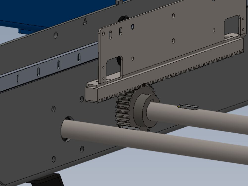
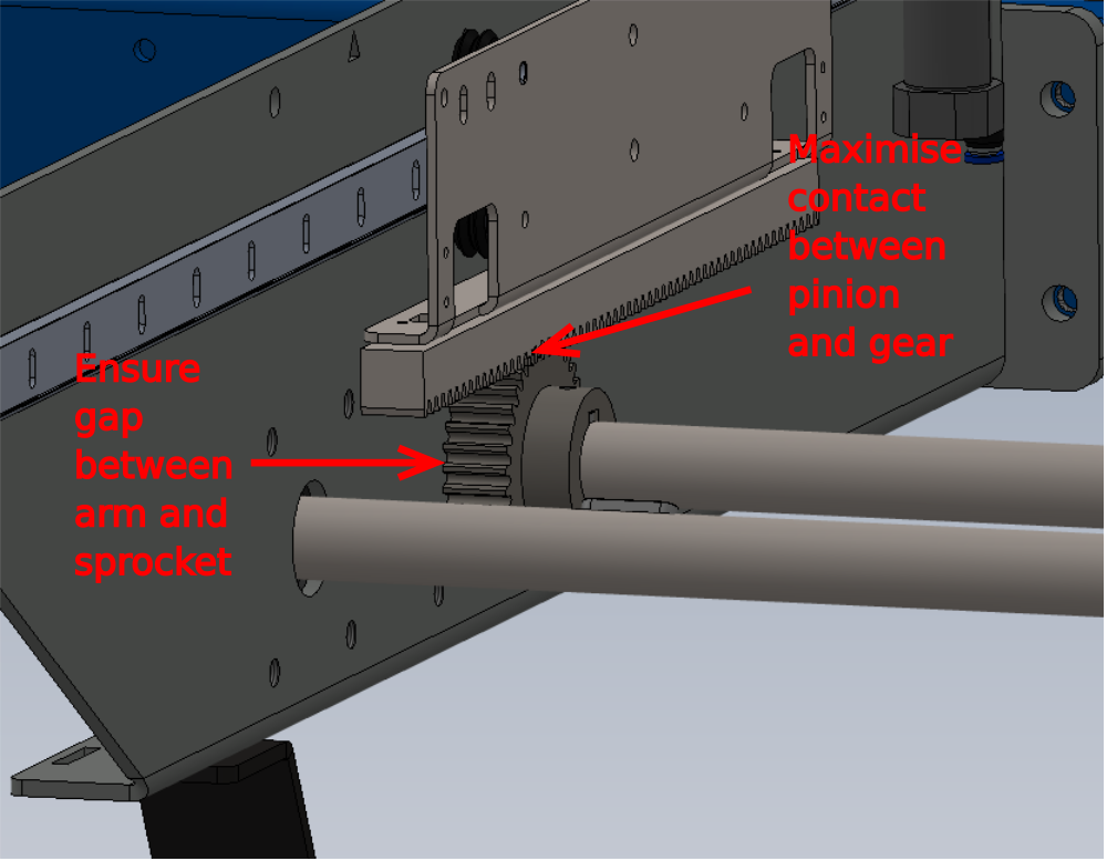
Étape 4 - Set pinion position
9 off pinions can now be set in position and finalised
Set position of pinion to achieve as much contact as possible with drive rail, without contacting side of support arm
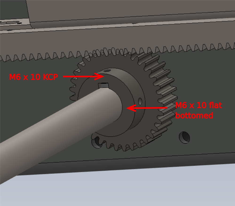
Étape 5 - Lock Pinion
lock each pinion in position as follows.
M6 x 10 kcp Grubscrew in hole that contacts key on shaft
M6 x 10 flat bottomed grubscrew on fixing hole that contacts directly onto shaft
Draft
 Français
 English
 Deutsch
 Español
 Italiano
 Português