| [version en cours de rédaction] | [version en cours de rédaction] |
| Ligne 66 : | Ligne 66 : | ||
Pen mark all fasteners to show finalised</translate> | Pen mark all fasteners to show finalised</translate> | ||
|Step_Picture_00=R0015086_Assemble_Pneumatics_on_to_electrical_cabinet_loctite_243.png | |Step_Picture_00=R0015086_Assemble_Pneumatics_on_to_electrical_cabinet_loctite_243.png | ||
| + | }} | ||
| + | {{Tuto Step | ||
| + | |Step_Title=<translate>Bush fitting Updated</translate> | ||
| + | |Step_Content=<translate>Before assembling Rod end P0000049 to cylinder, 2 off B0001106 bushes must be fitted as shown</translate> | ||
| + | |Step_Picture_00=R0015279_Align_Backfences_Screenshot_2025-01-07_143455.png | ||
}} | }} | ||
{{Tuto Step | {{Tuto Step | ||
Version actuelle datée du 7 janvier 2025 à 15:40
Instructions to bench assemble take up parts
Sommaire
- 1 Introduction
- 2 Étape 1 - Unless otherwise stated
- 3 Étape 2 - Bush fitting Updated
- 4 Étape 3 - Assemble cylinder unit
- 5 Étape 4 - Mounting bracket assembly
- 6 Étape 5 - Assemble arm
- 7 Étape 6 - Assemble arm to bracket
- 8 Étape 7 - Attach bearing block
- 9 Étape 8 - Assemble bump stop
- 10 Étape 9 - Lubrication
- 11 Commentaires
Introduction
Tools Required
Standard hex key set
Standard spanner set
Parts Required
D0008281 Takeup Boss Cap x 4
D0015581 Fixed Pivot Bracket x 4
D0015584 Cylinder Trunnion Plate x 1
D0015590 Takeup Arm ZX5 x4
D0015593 Takeup Arm Pin ZX5 x 4
D0015595 Takeup Arm Washer 4mm x 4
D0015596 Takeup Bearing Block Short x 4
D0015605 Fixed Pivot Bracket End Plate x 4
D0015736 Hard Stop Backplate x 1
D0015737 Hard Stop Shaft x 1
M0001077 Rubber bump stop M6 x 1
P0000010 Elbow Adaptor 6mm - 1/8 BSPT (Taper thread) x 1
P0000049 Cylinder Spherical Bearing M10 x 1.25 x 1
P0001075 Trunnion Pin for CG1 Cylinder x 1
P0001076 Trunnion Bracket for CG1 x 1
P0001112 Cylinder 32 x 125s Locking
P0001198 Fitting: Speed Controller 1/8" x 6mm Tube
Étape 1 - Unless otherwise stated
Use locktite 243 on all fasteners
Use loctite 572 on all threaded pneumatic connection
Pen mark all fasteners to show finalised
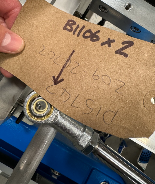
Étape 2 - Bush fitting Updated
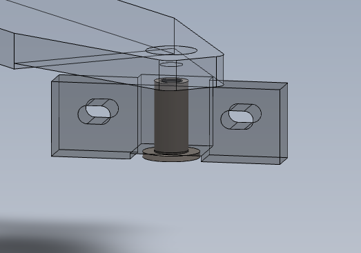
Before assembling Rod end P0000049 to cylinder, 2 off B0001106 bushes must be fitted as shown
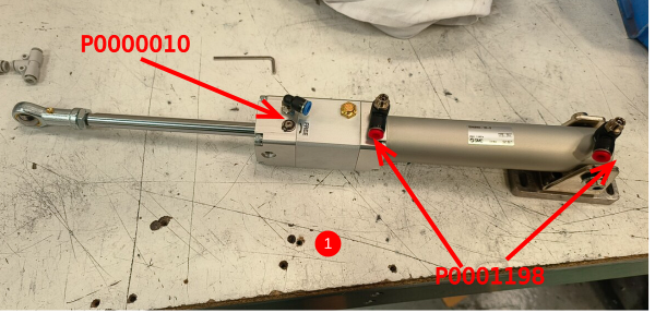
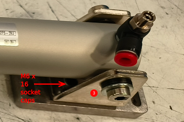
Étape 3 - Assemble cylinder unit
1 Fit air fittings PP0001198 2 off and P0001198 1 off as shown
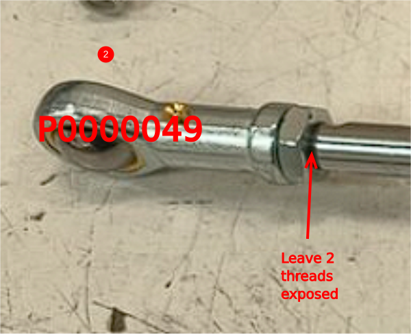
2 Attach P0000049 Cylinder Spherical Bearing to cylinder,use adhesive and finalise lock nut . Leave 2 threads exposed
3 Attach Cylinder clevis end using parts
P0001075 Trunnion Pin for CG1 Cylinder x 1
P0001076 Trunnion Bracket for CG1 x 1
Attach with M6 x 16 socket caps
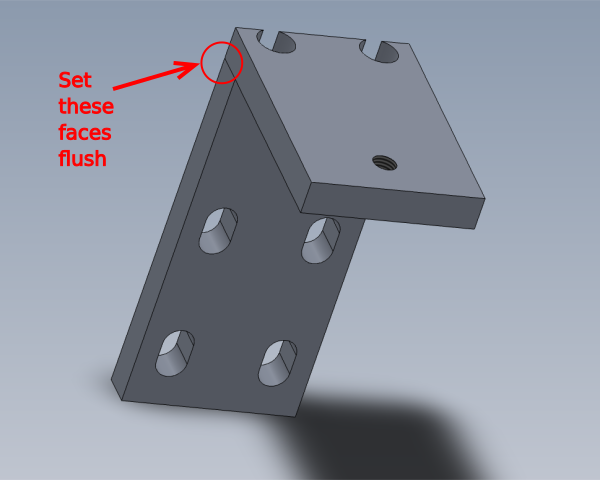
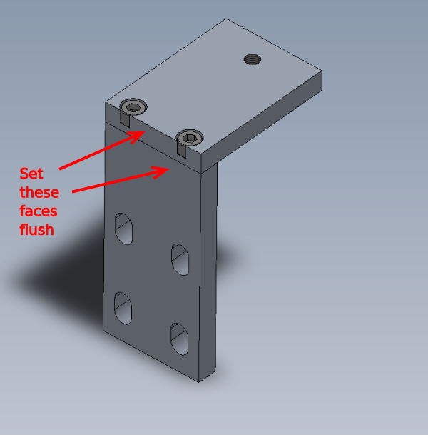
Étape 4 - Mounting bracket assembly
4 off
1 Combine D0015605 and D0015581 and fasten with 2 off M6 x 16 socket caps
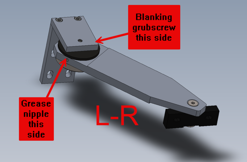
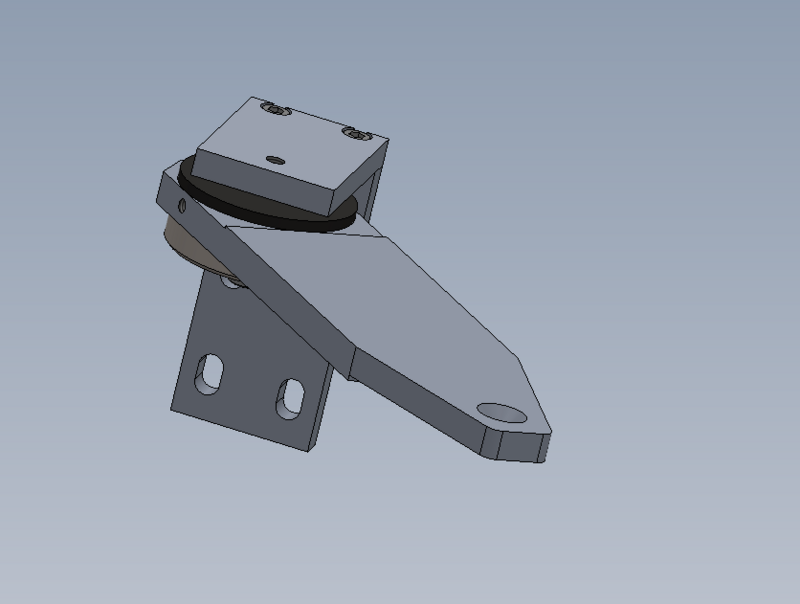
Étape 5 - Assemble arm
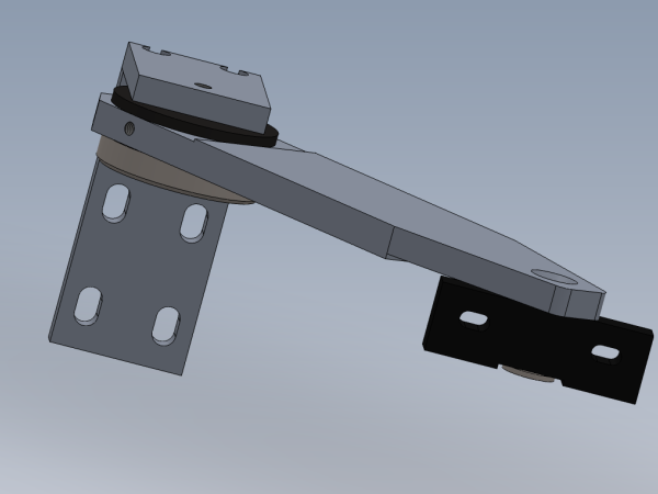
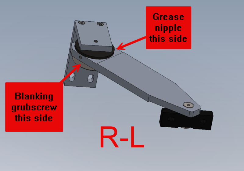
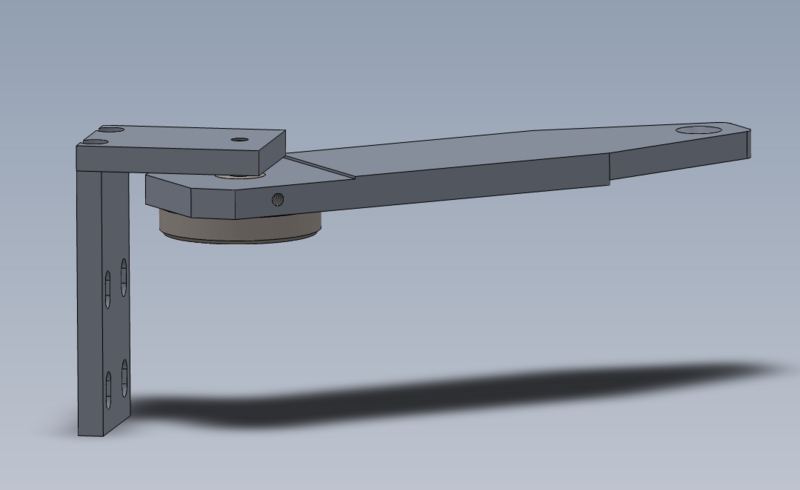
Following assembly is handed . Please see diagrams for correct assembly for appropriate hand of machine
4 off
Assemble arm parts as shown
Add M6 straight grease nipple to indicated face
Add M6 x 10 grubscrew to indicated face
Étape 6 - Assemble arm to bracket
4 off
Use M8 x 40 socket cap with heavy M8 washer to combine parts as shown . Use loctite 270 on M8 socket cap
Once bolt is finalised, check arm rotates smoothly when the bracket is held
Étape 7 - Attach bearing block
4 off
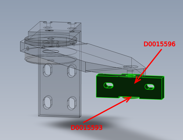
Insert D0015593 pin into takeup bearing block D0015596 and secure to arm using M8 x 30 Countersunk bolt and use Loctite 270 to fix
Check that D0015596 block turns freely once fastened
Étape 8 - Assemble bump stop
1 off
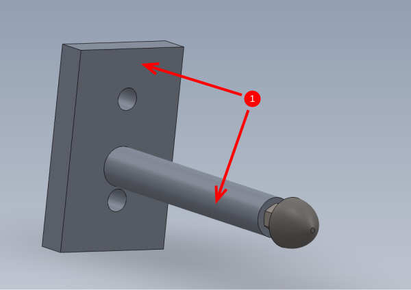
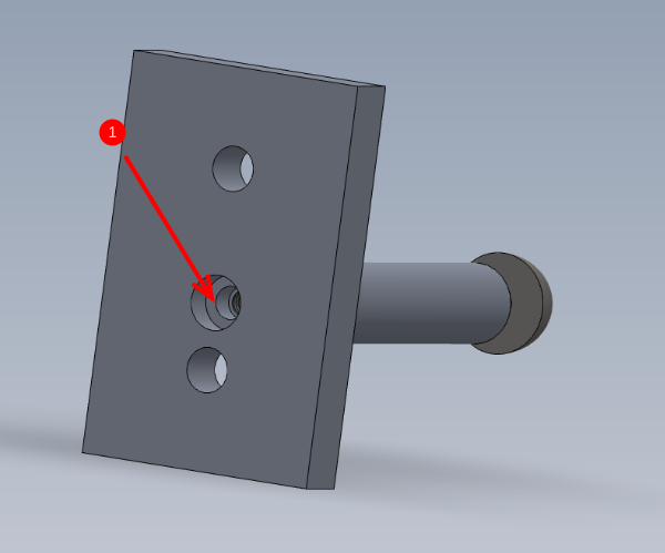
1 Mount D0015737 shaft to D0015736 Backplate using M6 x 16 socket cap
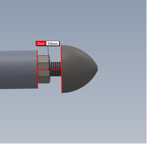
2 Attach bump stop M0001077 with M6 standard nut, use loctite 243 and set to dimension shown
Étape 9 - Lubrication
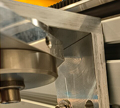
4 off arms should be lubricated with grease gun and trojan grease via greasing point
Draft


 Français
 English
 Deutsch
 Español
 Italiano
 Português