| [version en cours de rédaction] | [version en cours de rédaction] |
| Ligne 174 : | Ligne 174 : | ||
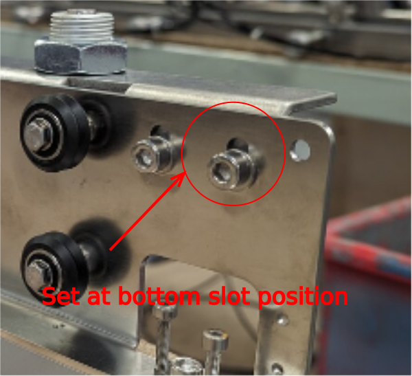
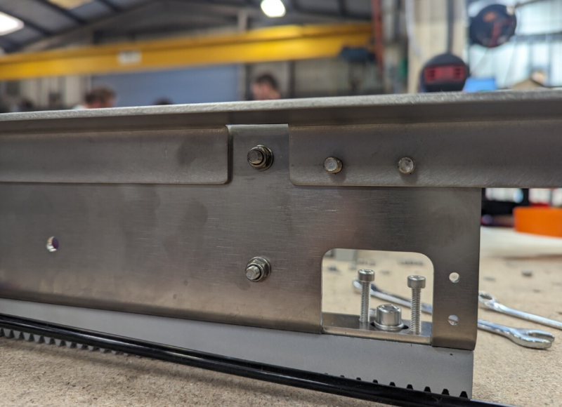
| − | Ensure plate is mounted parallel and at | + | Ensure plate is mounted parallel and at lowest point in slots</translate> |
|Step_Picture_00=R0015288_Bench_Assemble_Transfer_slider_units_and_Cylinder_Rails_Screenshot_2023-09-20_153153.png | |Step_Picture_00=R0015288_Bench_Assemble_Transfer_slider_units_and_Cylinder_Rails_Screenshot_2023-09-20_153153.png | ||
|Step_Picture_01=R0015288_Bench_Assemble_Transfer_slider_units_and_Cylinder_Rails_Screenshot_2023-11-27_110240.png | |Step_Picture_01=R0015288_Bench_Assemble_Transfer_slider_units_and_Cylinder_Rails_Screenshot_2023-11-27_110240.png | ||
Version actuelle datée du 22 décembre 2023 à 09:42
bench assembly details for bench assembly of pneumatic transfer rails
Sommaire
- 1 Introduction
- 2 Étape 1 - Unless otherwise stated
- 3 Étape 2 - Warning!!
- 4 Étape 3 - Check D0015573 for rework
- 5 Étape 4 - Air fittings to cylinders
- 6 Étape 5 - Attach cylinders
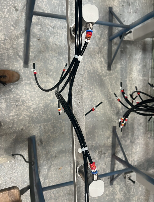
- 7 Étape 6 - Cut air pipes
- 8 Étape 7 - Connect Air pipes
- 9 Étape 8 - Loom pipes
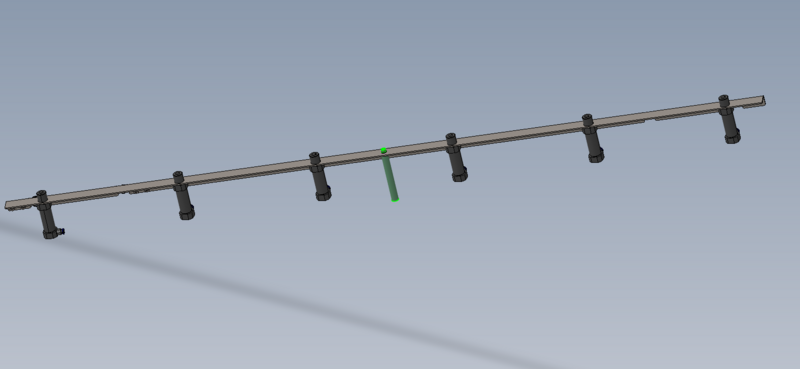
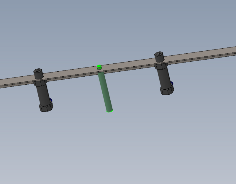
- 10 Étape 9 - Fit loom support spacer
- 11 Étape 10 - Assemble and fit concentric journal
- 12 Étape 11 - Assemble and fit Eccentric journal
- 13 Étape 12 - Attach to transfer rail
- 14 Étape 13 - Assemble drive journals concentric
- 15 Étape 14 - Assemble drive journals eccentric
- 16 Étape 15 - Attach drive rack
- 17 Étape 16 - Attach to cylinder rail
- 18 Commentaires
Introduction
Tools Required
Standard hex key set
Standard spanner set
Parts Required
B0001160 Delrin Dual V Wheel Kit x 48
B0001161 Spacer: Concentric - Delrin Dual V Wheel x 24
B0001162 Spacer: Eccentric - Delrin Dual V Wheel x 24
D0015255 Rack: Mod2 360 Long x 8
D0015551 Rack Mounting Plate x 8
D0015572 Slideway Connection Plate (2018) x 8
D0015573 Transfer Cylinder Bracket x 8
D0015576 Pneumatics Support Spacer x 8
D0015599 Transfer Cylinder Bracket Brace x 8
P0000007 Straight Adaptor 6mm - 1/8 BSP tapered thread x 48
P0001111 Cylinder: Ø25 x 25S Cut Shaft x 48
R0015093 Bench Assemble Transfer Beam x 8
Étape 1 - Unless otherwise stated
Use Loctite 243 on all fasteners
Use Loctite 570 on all threaded pneumatic connections
Pen mark all bolts when finalised
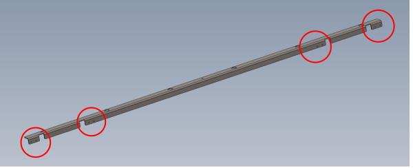
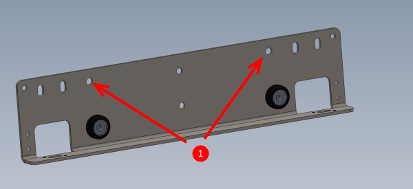
Étape 3 - Check D0015573 for rework
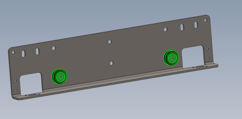
8 off Indicated holes should be 6.5mm clearance not M6 tapped
If holes are tapped, rework and drill to 6.5mm
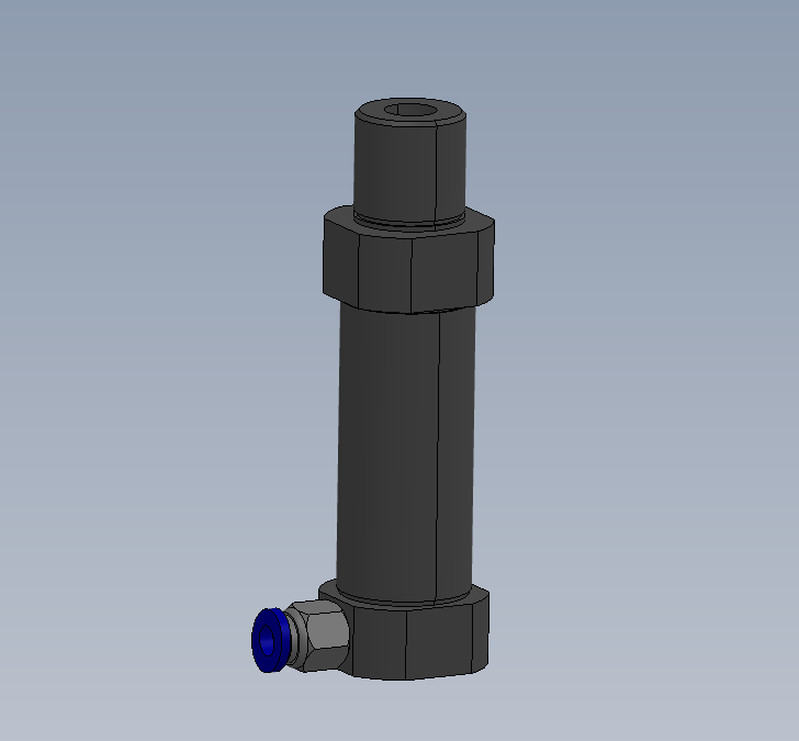
Étape 4 - Air fittings to cylinders
Attach P0000007 Straight Adaptor 6mm - 1/8 BSP tapered thread to P0001111 Cylinder: Ø25 x 25S Cut Shaft as shown
48 in total
Étape 5 - Attach cylinders
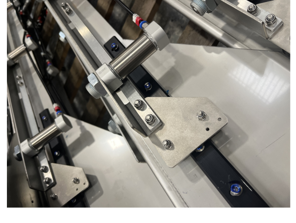
Attach cylinders to D0015573 Transfer Cylinder Bracket as shown
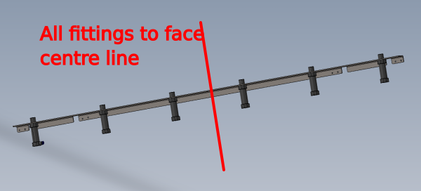
Air fittings to face directions shown
Étape 6 - Cut air pipes
cut and label the following pipes
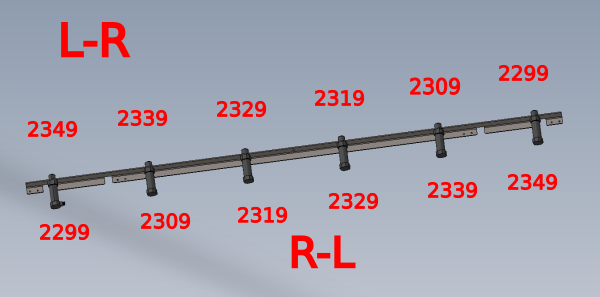
8 off 6mm black pipes @ 1050mm labelled as 2349 both ends
8 off 6mm black pipes @ 800mm labelled as 2339 both ends
8 off 6mm black pipes @ 500mm labelled as 2329 both ends
8 off 6mm black pipes @ 500mm labelled as 2319 both ends
8 off 6mm black pipes @ 800mm labelled as 2309 both ends
8 off 6mm black pipes @ 1050mm labelled as 2299 both ends
Étape 7 - Connect Air pipes
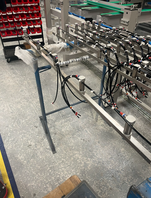
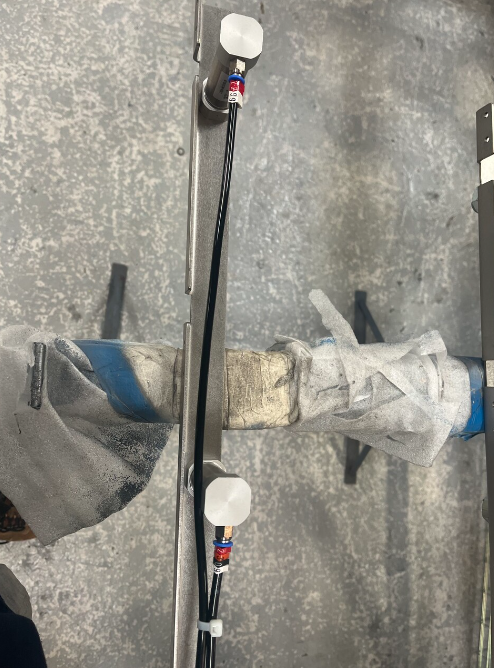
Connect air pipes as shown on each cylinder rail
L-R and R-L connections shown . Connect to suit handing of machine
Étape 9 - Fit loom support spacer
Fit D0015576 Pneumatics Support Spacer to each assembled rail using M6 x 16 socket caps and A form washer
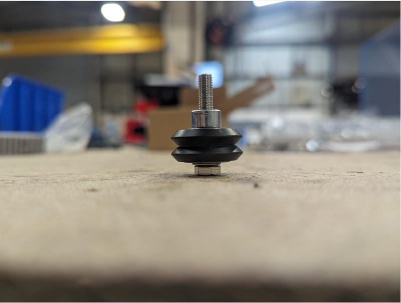
Étape 10 - Assemble and fit concentric journal
8 off in total
Fit concentric journal as shown to D0015572 Slideway Connection Plate
Assemble in this order
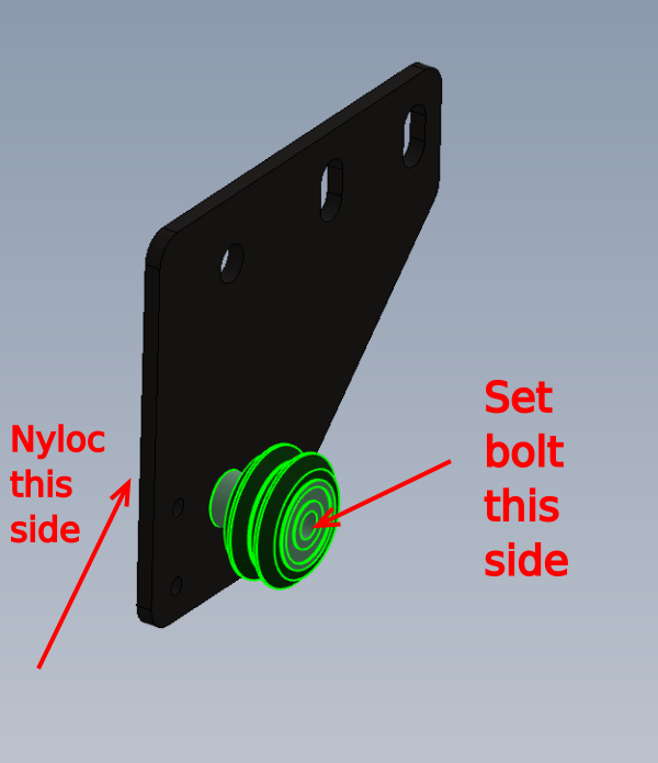
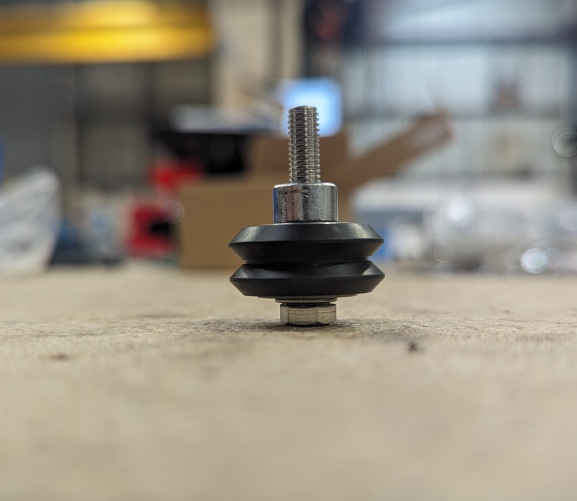
M5 x 30 set bolt- M5 A form washer- Delrin wheel assembly B0001160- spacer B0001161 - Main assembly - A form washer- M5 Nyloc nut
Étape 11 - Assemble and fit Eccentric journal
8 off
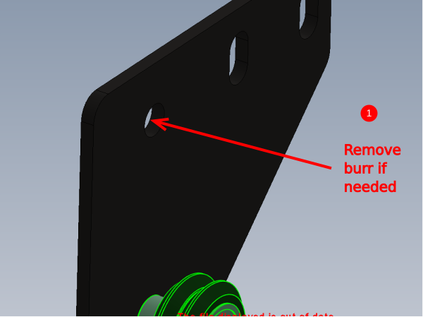
1 Check that part B0001162 sits flush into hole on mounting plate. It may be required to remove burrs from manufacture to achieve this
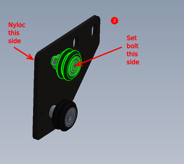
2 Attach delrin wheel in this order.
M5 x 30 Set bolt-M5 A form washer-Delrin Wheel (B0001160) -Eccentric cam(B0001162)- Assembly - M5 A Form Washer- M5 Nyloc nut
Do not add final tension to this wheel assembly as adjustment will be required at a later point
Étape 12 - Attach to transfer rail
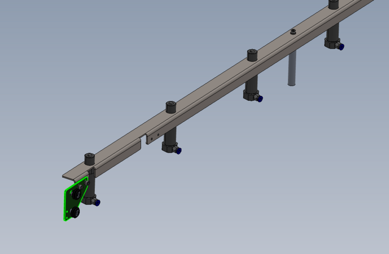
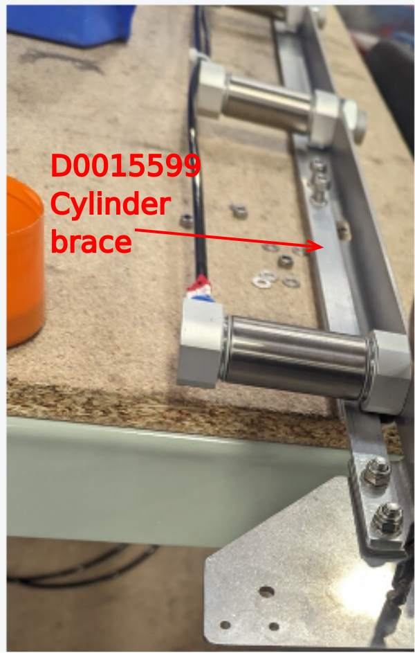
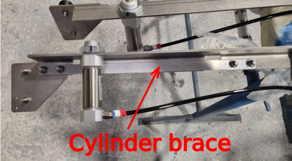
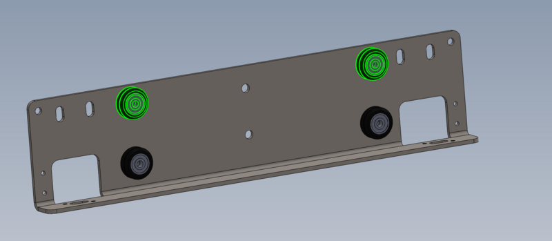
Combine D0015599 Transfer Cylinder Bracket Brace as shown
Use M6 x 20 socket caps, M6 a form washers and M6 nylocs to fix journal plate to transfer rail
Ensure plate is mounted parallel and at lowest point in slots
Étape 13 - Assemble drive journals concentric
8 off in total
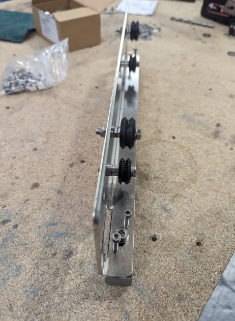
Fit 2 off concentric journals as shown to D0015551 Rack Mounting Plate
Assemble in this order
M5 x 30 set bolt- M5 A form washer- Delrin wheel assembly B0001160- spacer B0001161 - Main assembly - A form washer- M5 Nyloc nut
Étape 14 - Assemble drive journals eccentric
1 Check that part B0001162 sits flush into hole on mounting plate. It may be required to remove burrs from manufacture to achieve this
2 Attach delrin wheel in this order.
M5 x 30 Set bolt-M5 A form washer-Delrin Wheel (B0001160) -Eccentric cam(B0001162)- Assembly - M5 A Form Washer- M5 Nyloc nut
Do not add final tension to this wheel assembly as adjustment will be required at a later point
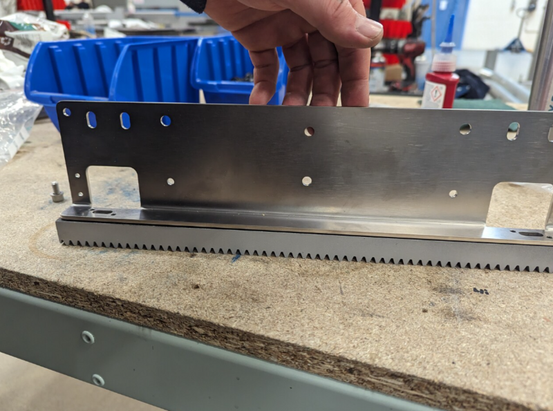
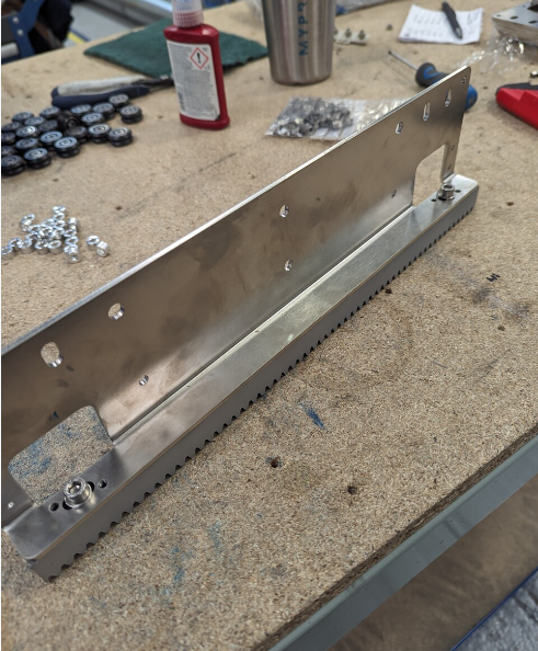
Étape 15 - Attach drive rack
Do not apply adhesive to these bolts
Ensure racks have been treated with ZG-90 galv spray
8 off
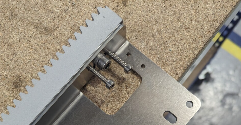
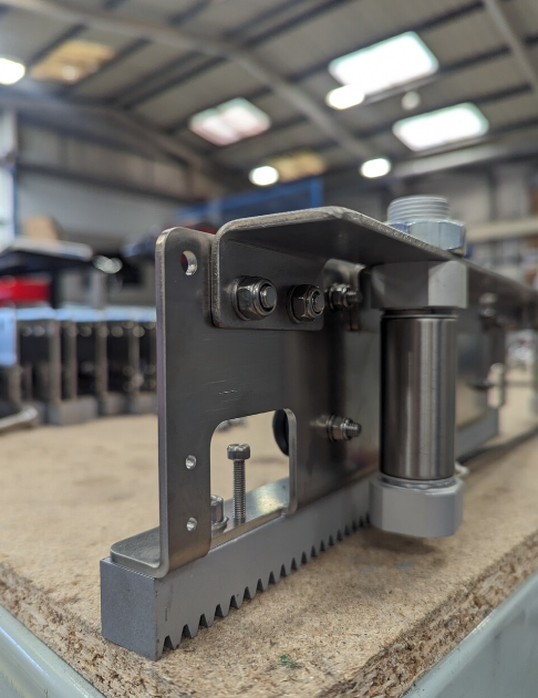
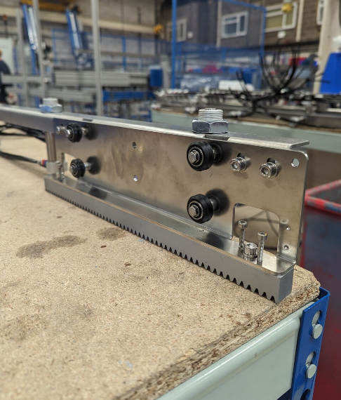
Attach D0015255 Rack: Mod2 360 Long as shown.
Fix with M6 x 20 socket caps and A form washers
Once Rack is fixed to mounting plate, add 4 off m4 x 20 socket caps as shown
Étape 16 - Attach to cylinder rail
Attach assembly to cylinder rail as shown , using 4 off M6 x 12 socket caps and A Form washers
Ensure bottom of slot adjustment is used as shown
Draft


 Français
 English
 Deutsch
 Español
 Italiano
 Português