| [version en cours de rédaction] | [version en cours de rédaction] |
| Ligne 243 : | Ligne 243 : | ||
| − | Set sensor position</translate> | + | Set sensor position to ensure minimal gap is present (-1mm) along full movement of travel . double check that no contact is made by sensor at any point of travel</translate> |
|Step_Picture_00=R0015317_Install_Rotary_Ring_Screenshot_2023-11-01_160857.png | |Step_Picture_00=R0015317_Install_Rotary_Ring_Screenshot_2023-11-01_160857.png | ||
}} | }} | ||
| Ligne 251 : | Ligne 251 : | ||
| − | + | Set sensor position to ensure minimal gap is present (-1mm) along full movement of travel . double check that no contact is made by sensor at any point of travel</translate> | |
|Step_Picture_00=R0015317_Install_Rotary_Ring_Screenshot_2023-11-01_161044.png | |Step_Picture_00=R0015317_Install_Rotary_Ring_Screenshot_2023-11-01_161044.png | ||
}} | }} | ||
Version du 4 décembre 2023 à 11:19
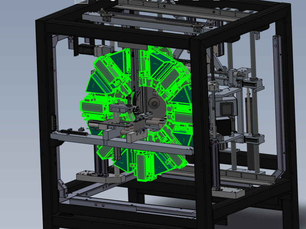
Installation procedure for rotary ring into mainframe

Difficulté
Difficile
Durée
4 heure(s)
Sommaire
- 1 Introduction
- 2 Étape 1 - Unless otherwise stated
- 3 Étape 2 - Safe operation
- 4 Étape 3 - Pre installation checks
- 5 Étape 4 - Fit Lifting strop to rotary ring
- 6 Étape 5 - Lift and position ring
- 7 Étape 6 - Lower to correct position
- 8 Étape 7 - Final Fix top bearing blocks
- 9 Étape 8 - Release weight
- 10 Étape 9 - Fix R axis gearbox and cable
- 11 Étape 10 - Finalise bottom bearing blocks
- 12 Étape 11 - Set R axis gearbox backlash
- 13 Étape 12 - Check R axis Backlash
- 14 Étape 13 - Finalise R axis gearbox
- 15 Étape 14 - Fit R axis servo motor
- 16 Étape 15 - Fit R axis gear box timing cover
- 17 Étape 16 - Set friction coupling
- 18 Étape 17 - Fit access plates
- 19 Étape 18 - Fit oil pots
- 20 Étape 19 - Fit ring bungs
- 21 Étape 20 - Fit Y axis hard stops
- 22 Étape 21 - Finalise Y axis leadscrew
- 23 Étape 22 - Fit Y axis Datum switch assembly
- 24 Étape 23 - Fit Z axis datum block assembly
- 25 Étape 24 - Fit ethercat cover
- 26 Étape 25 - Fit tool break assembly
- 27 Étape 26 - Connect Energy chain
- 28 Étape 27 - Quality check
- 29 Commentaires
Introduction
Tools Required
Standard Hex Key set
Standard spanner set
Lifting Strop
Overhead crane operation
Torque wrench
Soft hammer
Ring lubrication oil
Parts Required
A0000309 Domed Blanking Plug 19mm x 3
C0001123 Servo Motor: Beckhoff AM8062 18Nm 3000rpm x 1
D0000263 Stop Y Central x 1
D0002990E Strike Post ZX4 Mk5 x 1
D0002991 Switch carrier x 1
D0006061 Timing Belt cap x 1
D0007861 Y axis hard stop x 2
D0010756 Proximity Switch Mounting Block Reduced Size x 2
D0010894 Ethercat Cover ZX3/ZX4 x 1
D0015542 R Axis Motor Connector Cover x 1
E0000336 Sensor: M8; 2mm, PNP N/O, M8 conn x 2
H0007995 Rotary base cover plate x 2
M0000451 Plug and Elbow x 2
R0000971E Bench Assemble R Axis Gearbox
R0010260 Bench Assemble Tool Break Sensor
R0015138 Machining Head ZX4 Mk5 (Quad Plunge)
Étape 1 - Unless otherwise stated
Use locktite 243 on all fasteners
Use loctite 572 on all threaded pneumatic connection
Pen mark all fasteners to show finalised

Étape 2 - Safe operation
Installation of rotary ring requires the use of the overhead crane
Please ensure all safety requirements are met, and all employees are confident with the operation and installation progress before commencing work details

Étape 3 - Pre installation checks
Check z support bars are installed
Y axis leadscrew nut is not positioned in y axis bearing housing
Location dowels are fitted to Y axis bearing blocks
Étape 4 - Fit Lifting strop to rotary ring
Fit and position lifting strop onto rotary ring
Ensure strop is positioned correctly between spindles

Étape 5 - Lift and position ring
Use overhead crane to lift rotary ring assembly to align over the top of the machine centre main frame
Étape 6 - Lower to correct position
Slowly lower to correct position within machine centre assembly
Height setting is governed by bearing block alignment to back plate of rotary ring
Étape 7 - Final Fix top bearing blocks
Use M8 sockets to Finalise fixing between bearing blocks and rotary ring back plate
Finalise Fasteners

Étape 8 - Release weight
The lifting strop can now be released and removed from the rotary ring

Étape 9 - Fix R axis gearbox and cable
The lower section of the rotary rotary ring will require moving forward to enable r axis gearbox assembly to be fitted
Position Gearbox in place , along with R axis servo control cable
Light fix R axis gearbox in position

Étape 10 - Finalise bottom bearing blocks
Align and finalise bottom bearing blocks to rotary ring back plate

Étape 11 - Set R axis gearbox backlash
Set back lash on gearbox by hand
Push gearbox up towards centre of ring by hand and tighten holding fasteners
Étape 12 - Check R axis Backlash
Quality check for correct backlash between drive gears , requires 2 people
To complete this
Lock gearbox using 8mm hex key positioned in friction coupling of gearbox through access hole
Ensure gearbox is held in a fixed position
Rock rotary ring to check for presence of backlash. No backlash should be present , only minimal belt flex should be observed
Check backlash in 4 points equally spaced around rotary ring rotation

Étape 13 - Finalise R axis gearbox
Finalise all fasteners on r axis gearbox assembly
Étape 14 - Fit R axis servo motor
Add M0000031 edging strip to servo motor protection plate
Fit servo motor in conjuction with protection plate and ensuring servo connection cable is connected
Ensure servo plug is orientated correctly


Étape 15 - Fit R axis gear box timing cover
Fit timing cover

Étape 16 - Set friction coupling
Use torque wrench to set correct torque on r axis gearbox friction coupling
Fit gearbox blanking plug
Étape 17 - Fit access plates
Fit 2 off access plates

Étape 18 - Fit oil pots
Fit oil pots
Add ring oil
Add pot caps

Étape 19 - Fit ring bungs
Fit 3 off ring bungs

Étape 20 - Fit Y axis hard stops
Fit 2 off Y axis hard stops

Étape 21 - Finalise Y axis leadscrew
add and finalise Y axis leadscrew nut position

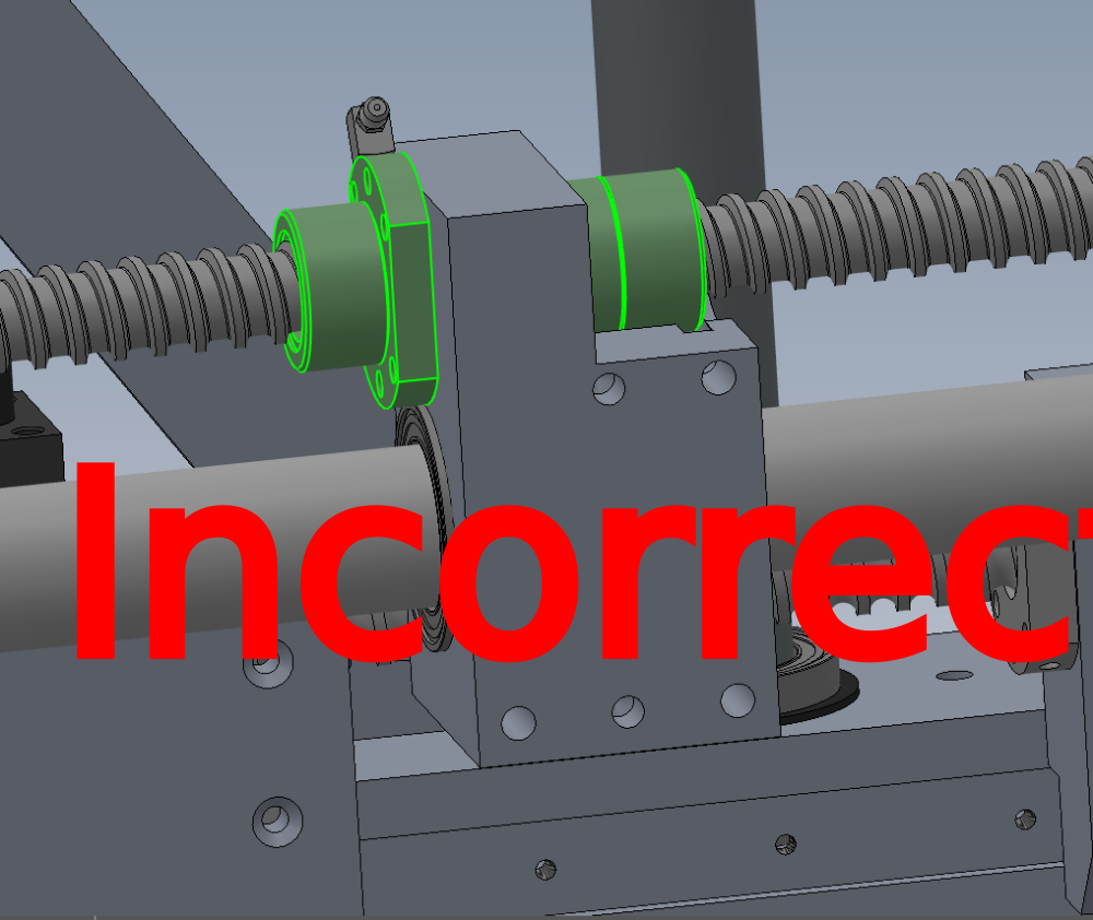
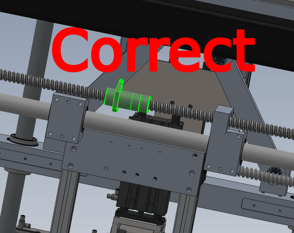
Étape 22 - Fit Y axis Datum switch assembly
Fit Y axis datum bracket, block and sensor
Set sensor position to ensure minimal gap is present (-1mm) along full movement of travel . double check that no contact is made by sensor at any point of travel

Étape 23 - Fit Z axis datum block assembly
Fit Z axis datum block assembly
Set sensor position to ensure minimal gap is present (-1mm) along full movement of travel . double check that no contact is made by sensor at any point of travel

Étape 24 - Fit ethercat cover
Fit ethercat cover
Dry fit temporary

Étape 25 - Fit tool break assembly
Fit tool break assembly

Étape 26 - Connect Energy chain
Connect energy chain to rotary ring

Étape 27 - Quality check
Quality check all fasteners are finalised
Draft
 Français
 English
 Deutsch
 Español
 Italiano
 Português