| [version en cours de rédaction] | [version en cours de rédaction] |
| Ligne 30 : | Ligne 30 : | ||
{{Materials}} | {{Materials}} | ||
{{EPI}} | {{EPI}} | ||
| + | {{Tuto Step | ||
| + | |Step_Title=<translate>Unless otherwise stated</translate> | ||
| + | |Step_Content=<translate>Use loctite 243 on all fasteners | ||
| + | |||
| + | Use Loctite 572 on all threaded pneumatic connections | ||
| + | |||
| + | Pen mark all bolts to show finalised</translate> | ||
| + | |Step_Picture_00=R0015086_Assemble_Pneumatics_on_to_electrical_cabinet_loctite_243.png | ||
| + | }} | ||
{{Tuto Step | {{Tuto Step | ||
|Step_Title=<translate>Attach Spherical bearings</translate> | |Step_Title=<translate>Attach Spherical bearings</translate> | ||
Version du 5 juillet 2023 à 09:56
Instructions for fitment of loader chain drive shafts
Introduction
Tools Required
Standard hex key set
Parts Required
B0000041 feather key 5 x 5 x 18 long
B0001152 Rigid Shaft Coupling Ø16
Pre Assembled R0015270 Bench assemble Shafts, bearings and sprockets
Étape 1 - Unless otherwise stated
Use loctite 243 on all fasteners
Use Loctite 572 on all threaded pneumatic connections
Pen mark all bolts to show finalised
Étape 2 - Attach Spherical bearings
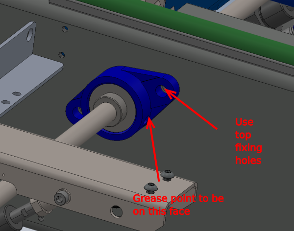
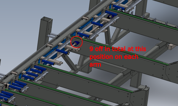
Attach 9 off B0001150 to load arms as shown . ensure correct position is used for mounting of bearings .
Use 2 off M8 x 30 socket countersink fasteners per bearing to align and fix to arms
Ensure greasing point of bearing is facing towards the front of the machine as shown
Étape 3 - Orientate drive shafts
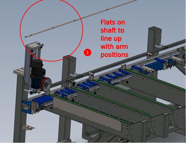
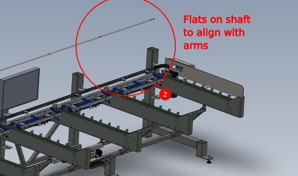
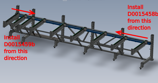
Orientation of drive shafts is as follows
1 D0015459b orientated as shown
2 D0015458b orientated as shown
Each flat on the shafts if orientated correctly will align with an arm position on the frame
Étape 4 - Prepare sprockets
Prepare sprockets to fit when shafts are installed
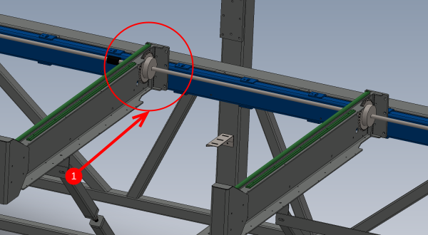
Sprocket B0001145 will require adding to shaft as it is fitted to main frame. Each arm will have a sprocket fitted in the position shown (1)
Étape 5 - Fit shafts
Install shafts from the directions shown , adding the B0001145 sprockets in their correct positions, as the shafts pass through the bearings . Do not close the gap between the 2 shafts in the centre of the machine until the next step is observed
Étape 6 - Install Shaft Coupling
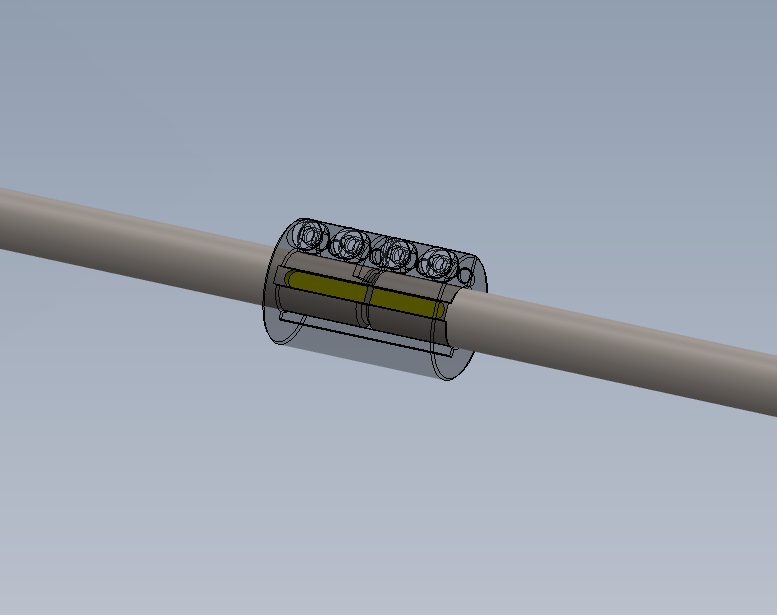
BFit shaft coupling B0001152 to one of shaft at the final stage of fitting.
Gap between shafts should be approximately 2mm
Once this is achieved fit 2 off b0000041 ( 1 to each shaft) align and tighten coupling in position
Overall position of the now combined drive shafts, bearing grubscrews and spockets will be finalised in a later dokit
Draft


 Français
 English
 Deutsch
 Español
 Italiano
 Português