| [version en cours de rédaction] | [version en cours de rédaction] |
| Ligne 73 : | Ligne 73 : | ||
{{Tuto Step | {{Tuto Step | ||
|Step_Title=<translate>Connect air</translate> | |Step_Title=<translate>Connect air</translate> | ||
| − | |Step_Content=<translate></translate> | + | |Step_Content=<translate>Cylinders require air to be able to adjust and level to the correct setting |
| + | |||
| + | |||
| + | If mains feed loom is already installed, this can be used, if not individual air feeds can be connected to feed cylinder | ||
| + | |||
| + | |||
| + | (attention required to this section, move to pneumatic test and incorporate of adjust timings of loom installation )</translate> | ||
}} | }} | ||
{{Tuto Step | {{Tuto Step | ||
| Ligne 144 : | Ligne 150 : | ||
| − | Transition should be smooth between roller bed assemblies</translate> | + | Transition should be smooth between roller bed assemblies, with no bumps or drops onto roller beds from previous ones</translate> |
| + | |Step_Picture_00=R0000711_Rotary_Base_Assembly_quality-assurance-testing.png | ||
}} | }} | ||
{{Notes}} | {{Notes}} | ||
Version du 4 juillet 2023 à 13:16
Fitting details for completed assemblies

Difficulté
Moyen
Durée
2 heure(s)
Introduction
Tools Required
Engineers level
2mm shim plates 2 off
2 meter straight edge
Standard Hex key Set
Standard spanner set
Parts Required
Completed Assemblies
R0015081
Étape 1 - Unless otherwise stated
All bolts to have Loctite 243 adhesive applied unless otherwise stated
All Threaded Pneumatic connections to have Loctite 570 applied
All bolts to be pen marked once adhesive applied and correct tension added

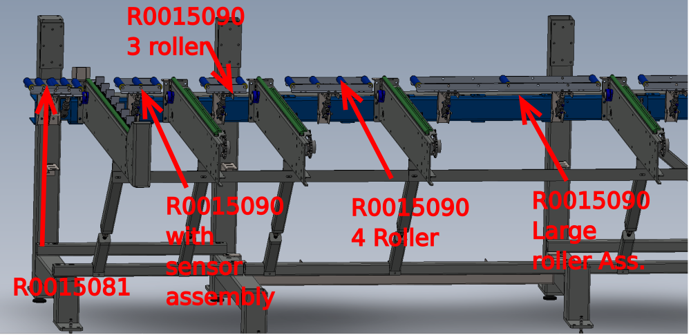
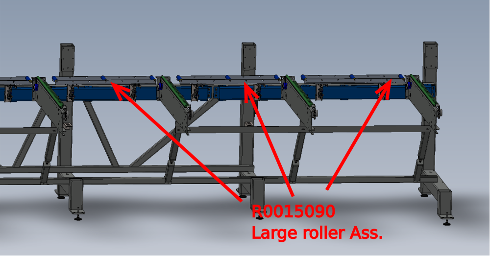
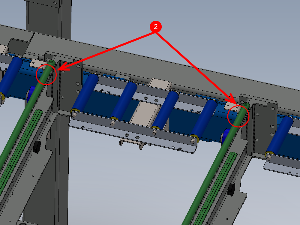
Étape 2 - Roller bed Positions
See Pictures for R0015081 and R0015090 roller bed locations

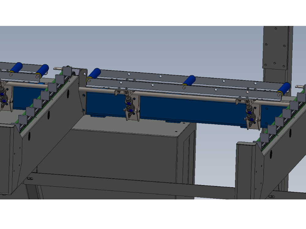
Étape 3 - Attach to Frame
1 Mount assemblies as shown using M8 x 25 socket caps and heavy M8 washers.
Do not apply Loctite 243 at this stage to bolts
Only apply enough tension to fasteners to hold roller assemblies true to the mounting face (Blue section)
2 Attach R0015081 using the same fasteners as above. Ensure the slots are used to align to the other roller bed assemblies as shown

Étape 4 - Connect air
Cylinders require air to be able to adjust and level to the correct setting
If mains feed loom is already installed, this can be used, if not individual air feeds can be connected to feed cylinder
(attention required to this section, move to pneumatic test and incorporate of adjust timings of loom installation )
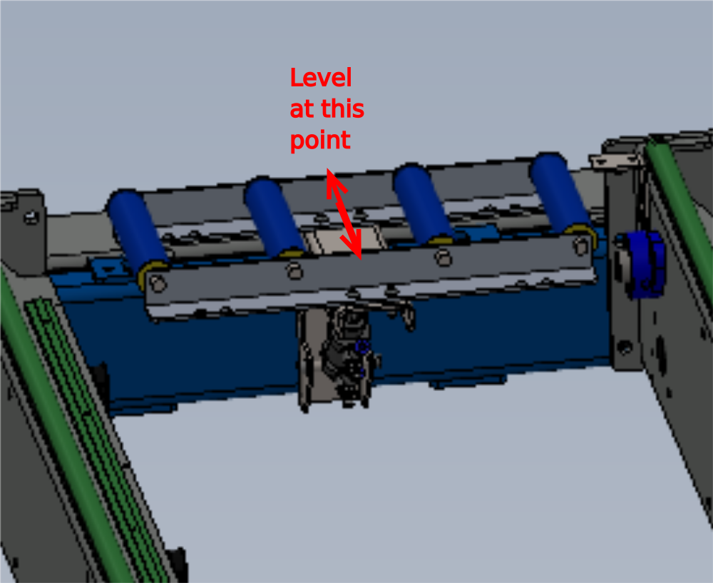
Étape 5 - Adjust Level
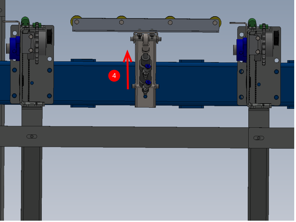
Using the cylinder stroke, Roller bed assemblies will need to be adjusted to a level position
1 Place engineers level above support bracket as shown
2 Wind back cylinder lock nut and apply Loctite 243 to thread of cylinder
3 Adjust cylinder stroke to achieve level
4 Lock off cylinder nut and confirm level has been maintained , if not adjust and tension lock nut.
5 (Skip to step 6 if a single bracket roller assembly )
Repeat on Second Bracket attached to assembly . Previous bracket setting must be checked after adjusting second bracket. Confirm both are level
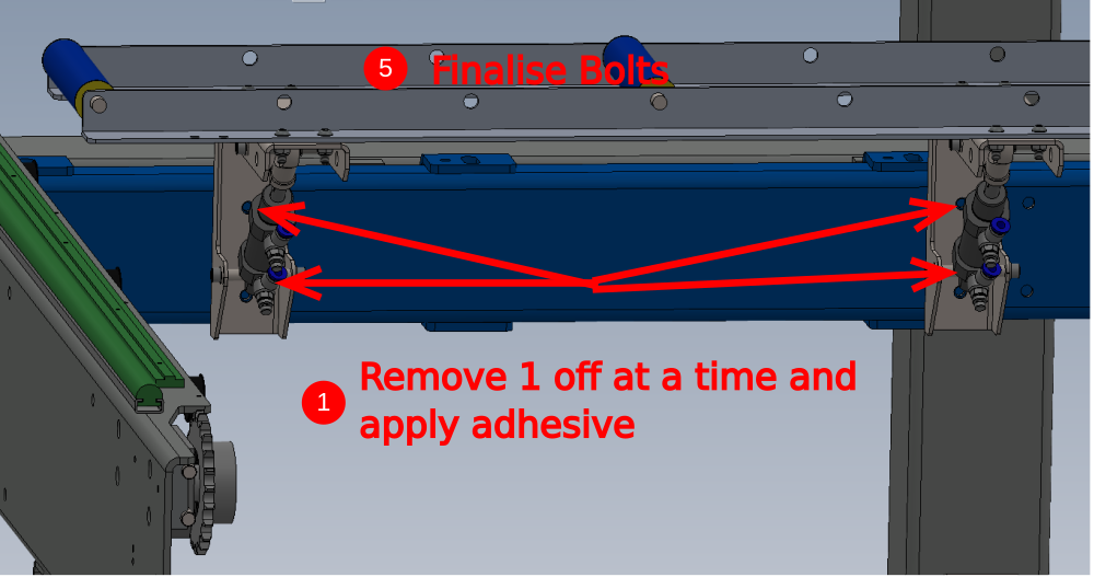
5 Mark Lock nut as complete when final setting is complete and locked off

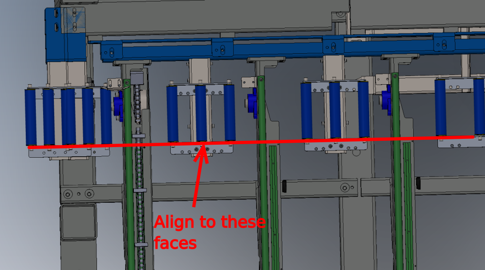
Étape 6 - Adjust and Set Height
1 Remove m8 Socket Caps individually on each roller bed as it is being adjusted for height and apply Loctite 243
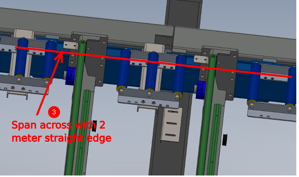
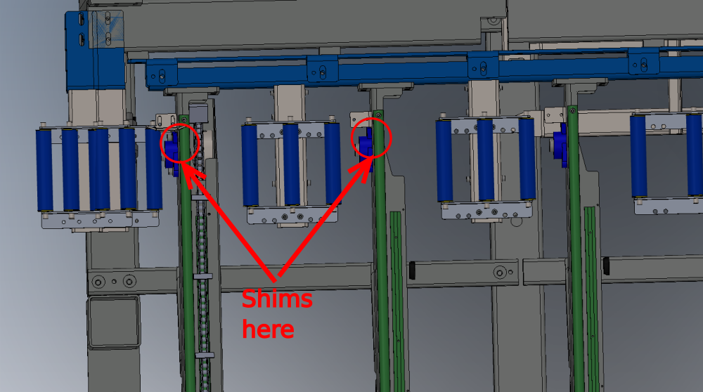
2 Place 2 off 2mm shims on top of green runner strips as indicated
3 Span across these with 2 meter straight edge
4 Lift roller assembly up to align with bottom face of straight edge
5 Tighten and finalise M8 Fixing bolts
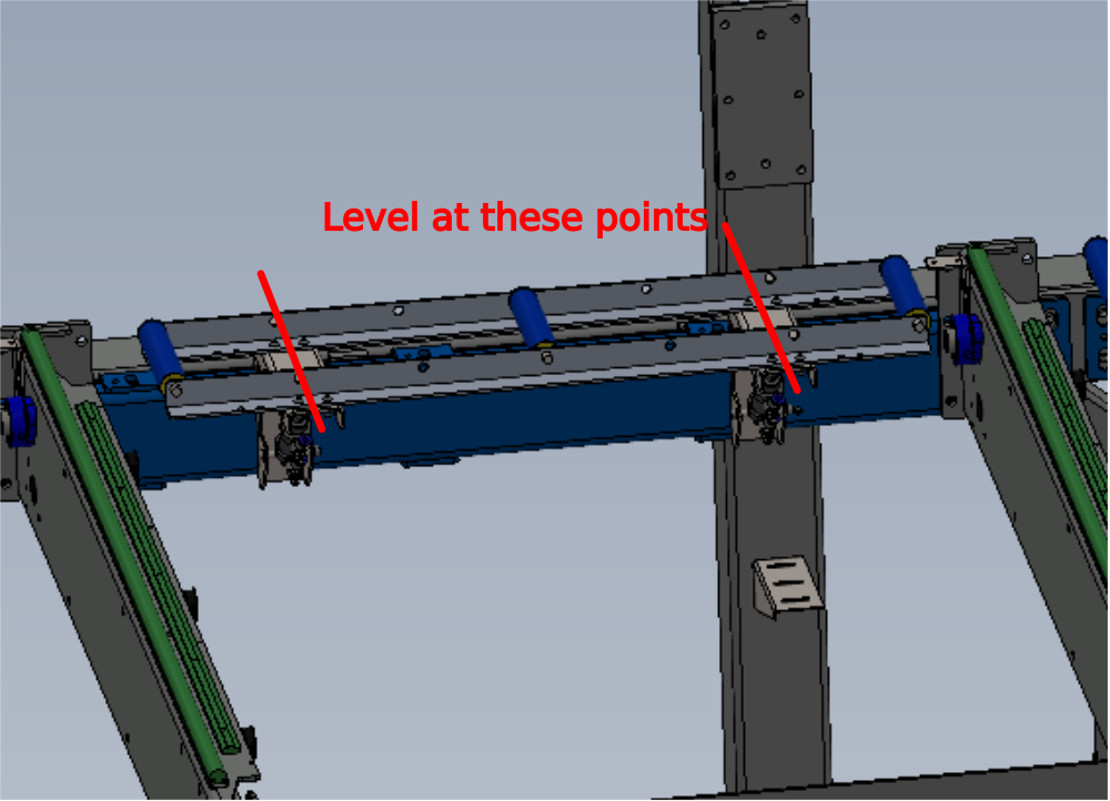
Étape 7 - Repeat
Repeat step 5 for all other roller bed assemblies except R0015081 using the same method
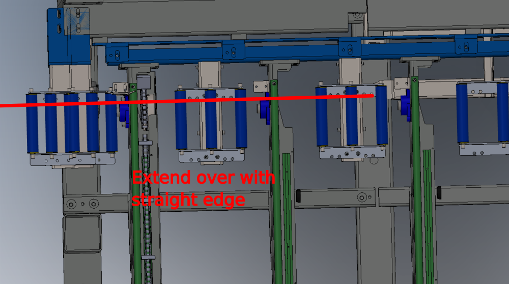
To level R0015081 place shims at points indicated and extend straight edge over to allow height setting
Étape 8 - Quality Check
Once all roller beds have been mounted and aligned , use the 2 meter straight edge to travel across the entire length of the finalised roller beds
Transition should be smooth between roller bed assemblies, with no bumps or drops onto roller beds from previous ones

Draft
 Français
 English
 Deutsch
 Español
 Italiano
 Português