| [version en cours de rédaction] | [version en cours de rédaction] |
| Ligne 30 : | Ligne 30 : | ||
{{Materials}} | {{Materials}} | ||
{{EPI}} | {{EPI}} | ||
| + | {{Tuto Step | ||
| + | |Step_Title=<translate>Unless otherwise stated</translate> | ||
| + | |Step_Content=<translate>Use Loctite 243 on all fasteners | ||
| + | |||
| + | Pen mark bolts to indicate finalised</translate> | ||
| + | |Step_Picture_00=R0000712E_Rotary_Trunking_Screenshot_2023-05-31_084239.png | ||
| + | }} | ||
{{Tuto Step | {{Tuto Step | ||
|Step_Title=<translate>Fit relay mounting plate</translate> | |Step_Title=<translate>Fit relay mounting plate</translate> | ||
Version du 2 juin 2023 à 12:19
Control installation
Introduction
Tools Required
Standard screwdriver set
Standard hex key set
Parts Required
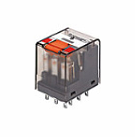
E0000519 Relay x 8
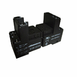
A0000160 Relay base x 8
C0001018 Ethercat box x 8
D0010806 Mounting plate x 8Étape 1 - Unless otherwise stated
Use Loctite 243 on all fasteners
Pen mark bolts to indicate finalised
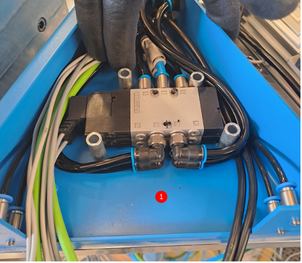
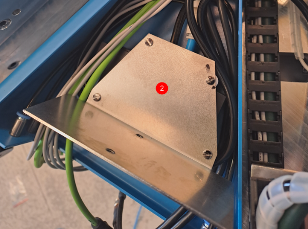
Étape 2 - Fit relay mounting plate
1 Segregate cables and pipes as shown in image
2 Mount D0010806 relay mounting base using 4 off M3x 25 pan head screws
3 Repeat for 7 off other connection boxes
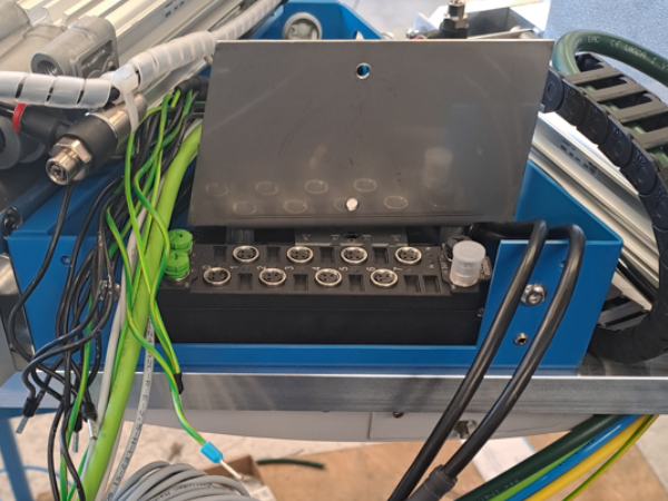
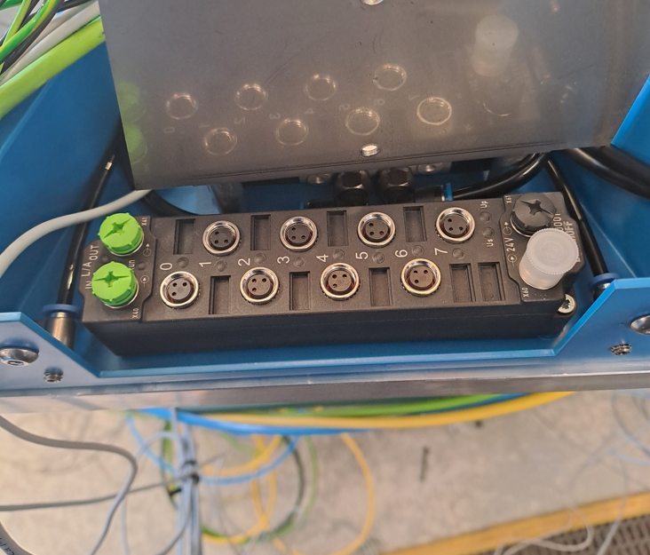
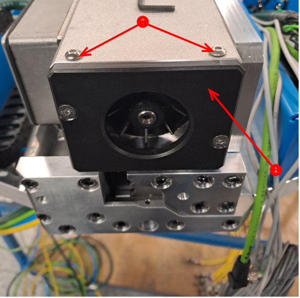
Étape 3 - Mount Ethercat boxes
Use 2 off M3 x 20 countersink posi screws to mount C0001018 Ethercat boxes to all 8 connection boxes
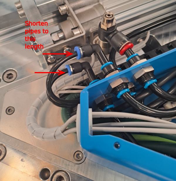
Étape 4 - Adjust Pipes
4 off connection boxes
4mm feed pipes to cylinders can now been adjusted in length to finalise
See image
Étape 5 - Check
1 Motor replacement end caps D0010908 are fitted
2 Blanking m4 x 6 button screws are fitted to single slide spindle motors
Étape 6 - Relay bases and relays
Ensure E0000519 relays and A0000160 relay bases are stored with ring ready for handover
Draft

 Français
 English
 Deutsch
 Español
 Italiano
 Português