| [version en cours de rédaction] | [version en cours de rédaction] |
| (2 révisions intermédiaires par le même utilisateur non affichées) | |||
| Ligne 66 : | Ligne 66 : | ||
#Expand I/O -> Devices-> Device (EtherCAT), Double click and open the Online tab. | #Expand I/O -> Devices-> Device (EtherCAT), Double click and open the Online tab. | ||
| + | #Update the Twincat3 folder firmware from \\mainserver\Data\Design\TwinCAT3\Firmware | ||
#Check the Drive you are going to update is in OP state and right mouse click on it. | #Check the Drive you are going to update is in OP state and right mouse click on it. | ||
| − | |||
#Select FIRMWARE UP. Navigate to the location of the firmware. Normally C:\TwinCAT\Functions\TE5950-Drive-Manager-2\Firmware\AX5000 | #Select FIRMWARE UP. Navigate to the location of the firmware. Normally C:\TwinCAT\Functions\TE5950-Drive-Manager-2\Firmware\AX5000 | ||
#Do the same process for the EEROM matching the version number. | #Do the same process for the EEROM matching the version number. | ||
| Ligne 197 : | Ligne 197 : | ||
6) Commutation P-0-150 as per Image | 6) Commutation P-0-150 as per Image | ||
| − | P-0-0057 Electrical commutation offset and set a value of | + | 7) P-0-0057 Electrical commutation offset and set a value of 69 deg</translate> |
|Step_Picture_00=GY_GZ_axis_setup_with_Jetter_Motors_GZ_Brake.png | |Step_Picture_00=GY_GZ_axis_setup_with_Jetter_Motors_GZ_Brake.png | ||
|Step_Picture_01=GY_GZ_axis_setup_with_Jetter_Motors_GZ_Tune.png | |Step_Picture_01=GY_GZ_axis_setup_with_Jetter_Motors_GZ_Tune.png | ||
|Step_Picture_02=GY_GZ_axis_setup_with_Jetter_Motors_GZ_Com_1.png | |Step_Picture_02=GY_GZ_axis_setup_with_Jetter_Motors_GZ_Com_1.png | ||
|Step_Picture_03=GY_GZ_axis_setup_with_Jetter_Motors_Z_P150_Mech_Offset.png | |Step_Picture_03=GY_GZ_axis_setup_with_Jetter_Motors_Z_P150_Mech_Offset.png | ||
| + | |Step_Picture_04=GY_GZ_axis_setup_with_Jetter_Motors_GZ_Elec_Com.png | ||
| + | |Step_Picture_04_annotation={"version":"2.4.6","objects":[{"type":"image","version":"2.4.6","originX":"left","originY":"top","left":0,"top":0,"width":800,"height":146,"fill":"rgb(0,0,0)","stroke":null,"strokeWidth":0,"strokeDashArray":null,"strokeLineCap":"butt","strokeDashOffset":0,"strokeLineJoin":"miter","strokeMiterLimit":4,"scaleX":0.75,"scaleY":0.75,"angle":0,"flipX":false,"flipY":false,"opacity":1,"shadow":null,"visible":true,"clipTo":null,"backgroundColor":"","fillRule":"nonzero","paintFirst":"fill","globalCompositeOperation":"source-over","transformMatrix":null,"skewX":0,"skewY":0,"crossOrigin":"","cropX":0,"cropY":0,"src":"https://stuga.dokit.app/images/thumb/d/da/GY_GZ_axis_setup_with_Jetter_Motors_GZ_Elec_Com.png/800px-GY_GZ_axis_setup_with_Jetter_Motors_GZ_Elec_Com.png","filters":[]},{"type":"wfellipse","version":"2.4.6","originX":"center","originY":"center","left":393.63,"top":58.85,"width":104.58,"height":76.18,"fill":"rgba(255,0,0,0)","stroke":"#FF0000","strokeWidth":2,"strokeDashArray":null,"strokeLineCap":"butt","strokeDashOffset":0,"strokeLineJoin":"miter","strokeMiterLimit":4,"scaleX":1,"scaleY":1,"angle":0,"flipX":false,"flipY":false,"opacity":1,"shadow":null,"visible":true,"clipTo":null,"backgroundColor":"","fillRule":"nonzero","paintFirst":"fill","globalCompositeOperation":"source-over","transformMatrix":null,"skewX":0,"skewY":0,"rx":52.29236668396256,"ry":38.09229189349284}],"height":110,"width":600} | ||
}} | }} | ||
{{Notes}} | {{Notes}} | ||
Version actuelle datée du 15 mai 2023 à 15:11
Autoflow MK4 GY&GZ axis setup with Jetter Motors
Sommaire
- 1 Introduction
- 2 Étape 1 - Initial Preparation
- 3 Étape 2 - GY Axis:
- 4 Étape 3 - GZ Axis
- 5 Étape 4 - Counterbalance
- 6 Étape 5 - CX5203 Firmware Upgrade
- 7 Étape 6 - Drive Manager 2 and Support Jetter Files
- 8 Étape 7 - Basic Assumptions
- 9 Étape 8 - GY setup Motor
- 10 Étape 9 - GY Setup FeedBack
- 11 Étape 10 - GY Setup Scaling
- 12 Étape 11 - GY Setup Tuning
- 13 Étape 12 - GY Setup Commutation step 1 P-0-150
- 14 Étape 13 - GY Setup Commutation angles(if necessary to change)
- 15 Étape 14 - GZ Setup
- 16 Commentaires
Introduction
WARNING:
The Jetter motor on the GZ axis has a brake. Releasing the brake without control could be harmful/dangerous.
Use the Air Counterbalance rig to assist if necessary.
Étape 1 - Initial Preparation
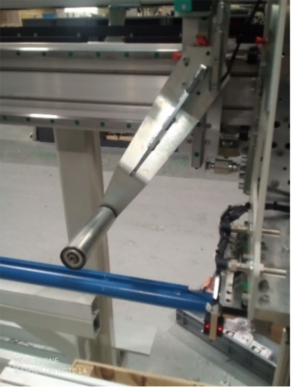
Ensure that the profile support arm is held out of the way to avoid marking the blue infeed arm.
Étape 2 - GY Axis:
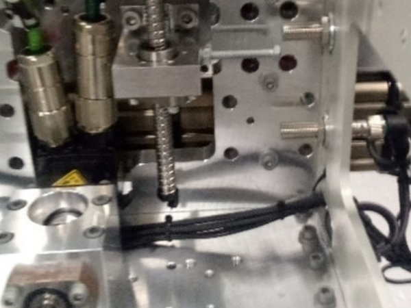
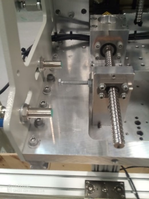
Check that proximity arm is in between the proximity sensor.
You should be able to turn the leadscrew by hand to move it.
Étape 3 - GZ Axis
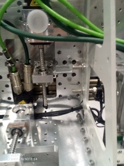
Check that proximity arm is in between the proximity sensor
This has a brake and you can only turn the leadscrew by hand if the counterbalance is fitted.
Étape 4 - Counterbalance
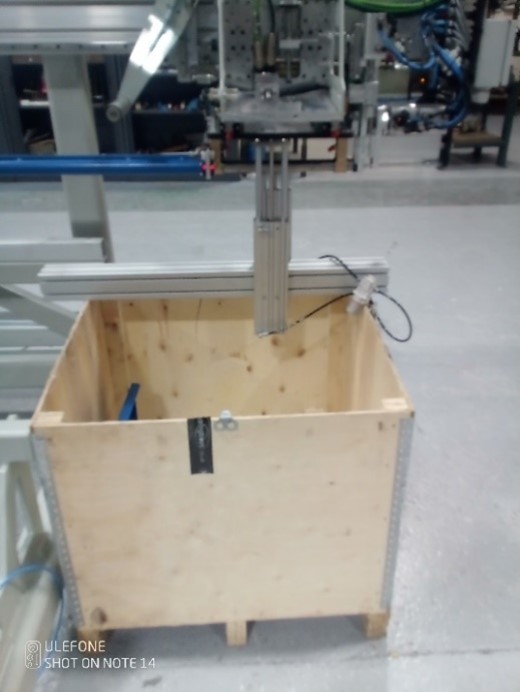
Counterbalance fitted under the carriage.
Adjust the pressure until you can turn the leadscrew of the GZ axis by hand. (6 bar)
.
Étape 5 - CX5203 Firmware Upgrade
The firmware on the CX5203 must be high enough to be supported under Drive manager 2.
Because you have to remove and add drives back into a project, create a new project just to update the drives.
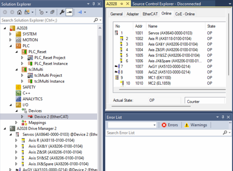
- Expand I/O -> Devices-> Device (EtherCAT), Double click and open the Online tab.
- Update the Twincat3 folder firmware from \\mainserver\Data\Design\TwinCAT3\Firmware
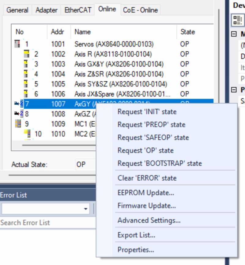
- Check the Drive you are going to update is in OP state and right mouse click on it.
- Select FIRMWARE UP. Navigate to the location of the firmware. Normally C:\TwinCAT\Functions\TE5950-Drive-Manager-2\Firmware\AX5000
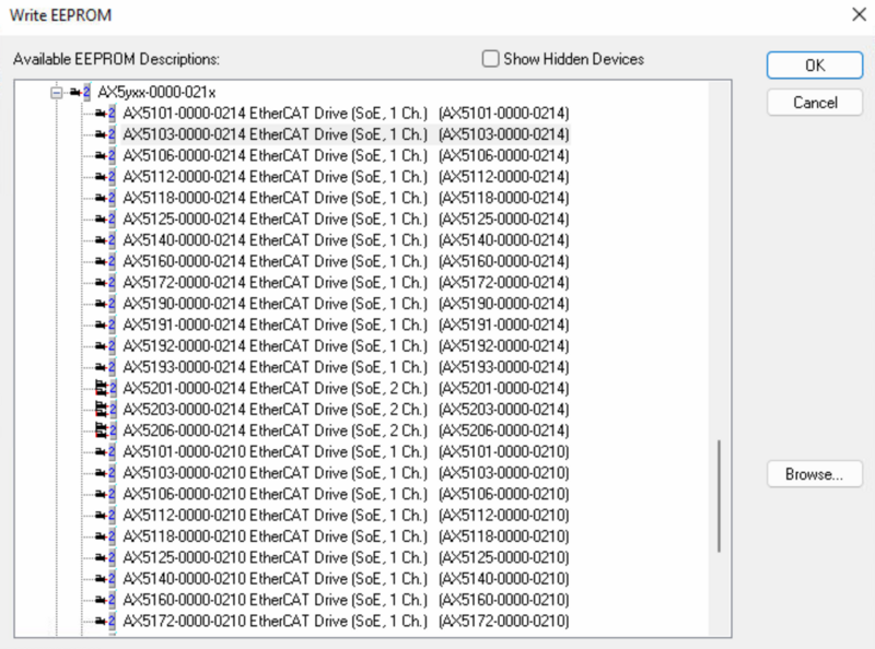
- Do the same process for the EEROM matching the version number.
- Check that you have the XML definition file for the version of firmware in C:\TwinCAT\3.1\Config\Io\EtherCAT\Beckhoff AX5xxx
- With this done you should be able to delete the drives and add them back and check under drive manager 2
Étape 6 - Drive Manager 2 and Support Jetter Files
Ensure Drive Manager 2 is installed (Version 1.1.60.0 minimum)
Copy the files from :
G:\Design\TwinCAT3\Other Motor Definition Files
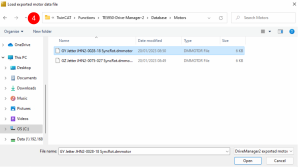
GY Jetter JHN2-0028-18 SyncRot.dmmotor
GZ Jetter JHN2-0075-027 SyncRot.dmmotor
to C:\TwinCAT\Functions\TE5950-Drive-Manager-2\Database\Motors
Étape 7 - Basic Assumptions
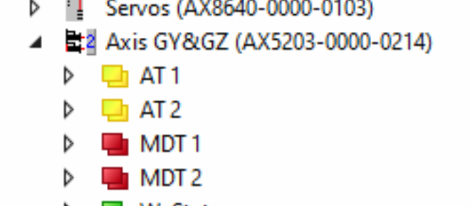
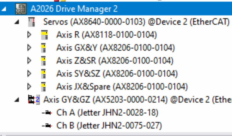
The Motors are connected to an AX5203 Drive
GY on the A channel
GZ on the B channel
The Drive is labelled GY & GZ
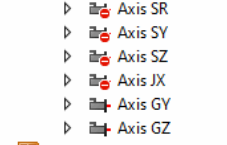
The channels are mapped to AXIS with appropriate names
A Driver Manager 2 Project exists with the Drives in it.
Étape 8 - GY setup Motor
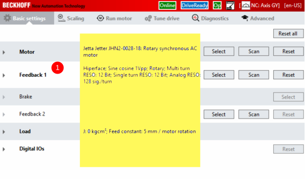
- Double click on GY axis (Ch A ) in drive manager 2 . You will not see the information highlighted yet.
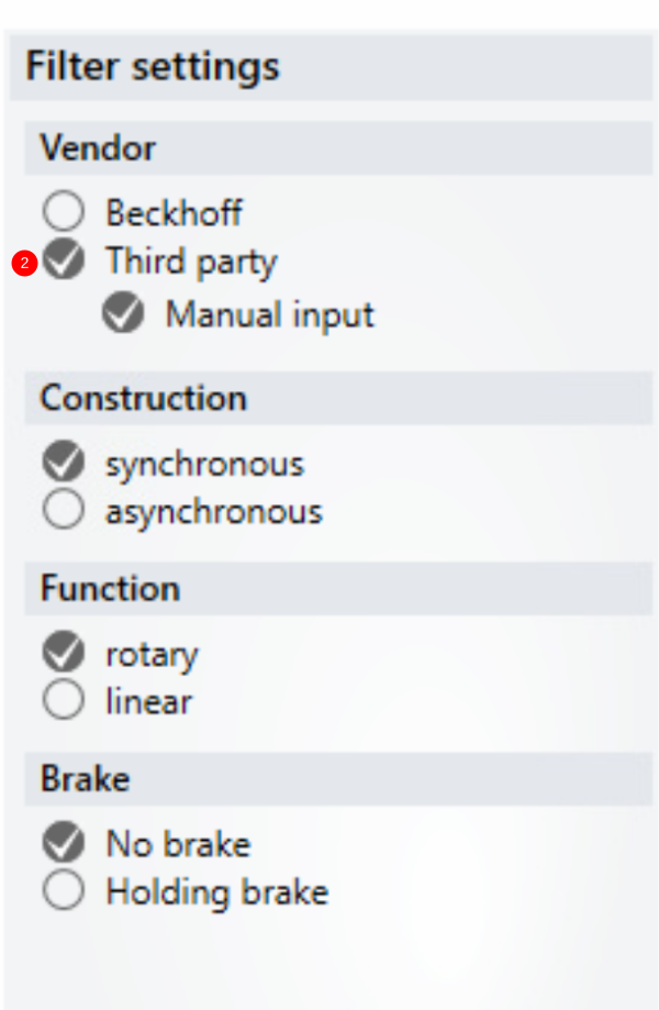
- For the Motor, press Select then select the filter options.
- Select Import.
- Move to the folder C:\TwinCAT\Functions\TE5950-Drive-Manager-2\Database\Motors
- Select the GY and Open
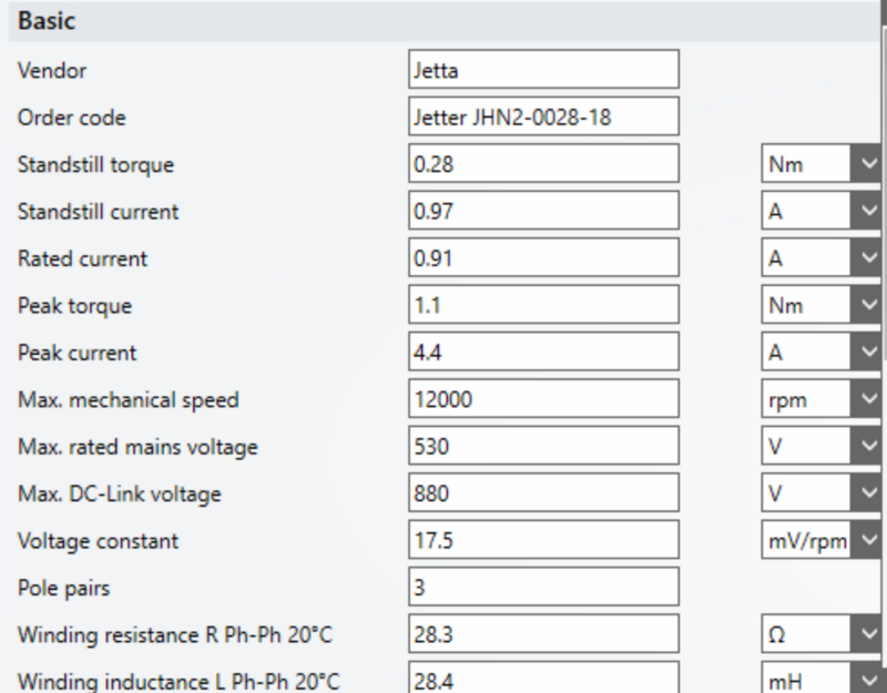
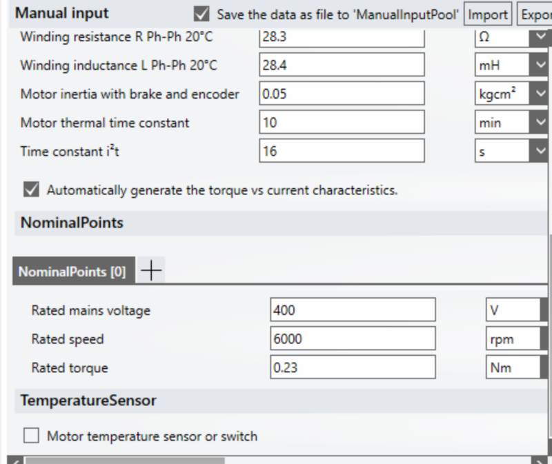
- The parameters should all match the screen shots.
Étape 9 - GY Setup FeedBack
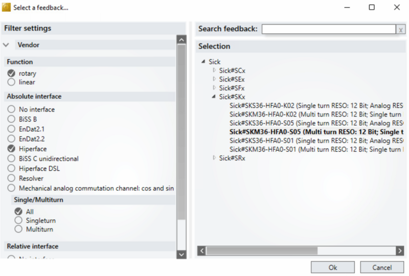
- From the Manager Screen, press Select to "Feedback 1"
- Under filter Select as shown (Hiperface being the important one)
- Expand Sick#SKx and select SKM36- HFA0-S05 and OK
Étape 10 - GY Setup Scaling
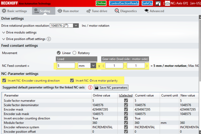
- Select the Scaling Tab
- Adjust the settings Highlighted.
- When checking the INVERT boxes you will get a request to activate it straight away. Do not bother as you have to activate all settings done later.
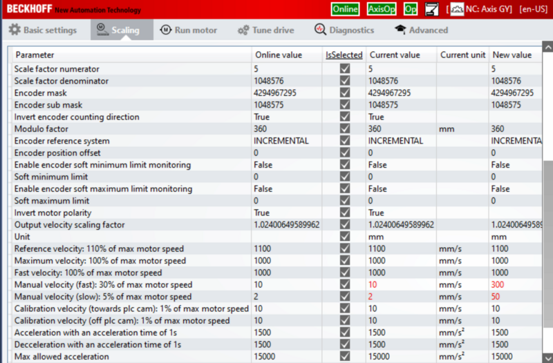
- Before you save the NC Parameters look at the values in red. If the new value is different to the Online value of the screen shot de-tick this selected box so that it does not update.
Étape 11 - GY Setup Tuning
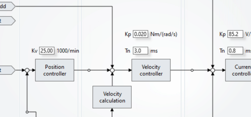
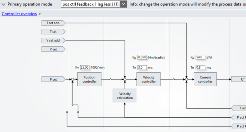
- Select the Tune Drive tab
- Set Kp = 0.02
- Set Kp=85.2
- Set Kv=25
- Set Tn=3.0
- Set Tn 0.8
Étape 12 - GY Setup Commutation step 1 P-0-150
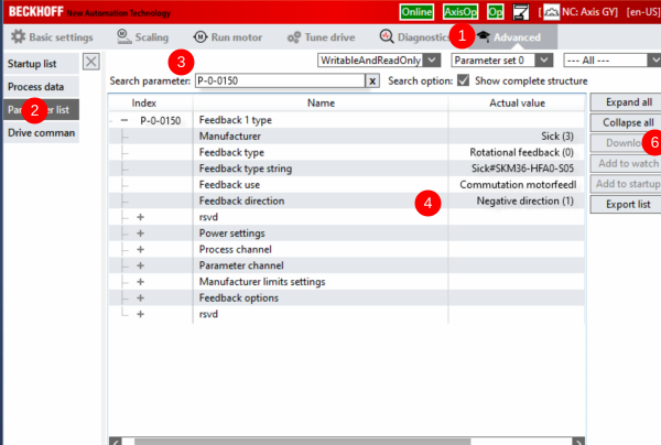
- Select th Advance tab
- Select Parameter List
- In search Type P-0-150
- Check the settings
- You may have to change the Feedback direction to Negative
- If you change it remember to press download after the change
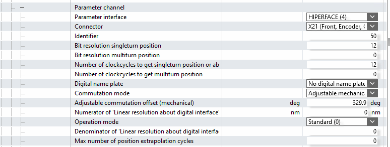
- Expand the "Parameter channel"
- Make sure that Commutation mode = Adjustable mechanical offset.
- Make sure Adjust commutation offset (Mechanical) is 0.0 deg
- Go to P-0-0057 Electrical commutation offset and set a value of 340 deg
Étape 13 - GY Setup Commutation angles(if necessary to change)
There are two forms of commutation set up, Mechanical and Electrical.
Mechanical is going to be 0 degrees and we are going to adjust the Electrical using the command P-0-0166
Étape 14 - GZ Setup
Repeat as for GY with the following changes:
1) Motor Set up - select the GZ jetter file
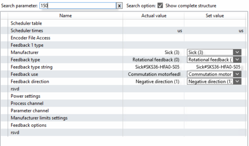
2) Feedback set to Sick#SKS36-HFA0-S05 (Single turn...)
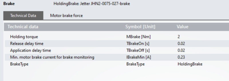
3) Brake parameters should be as per image
4) Scaling as per GY
5) Tune drive settings as per image.
6) Commutation P-0-150 as per Image
7) P-0-0057 Electrical commutation offset and set a value of 69 deg
Draft



 Français
 English
 Deutsch
 Español
 Italiano
 Português