| [version en cours de rédaction] | [version en cours de rédaction] |
(Page créée avec « {{Tuto Details |Description=<translate>Critical measurements and settings for an Autoflow infeed table</translate> |Categories=Software }} <translate><br /> = Method =... ») |
|||
| (5 révisions intermédiaires par le même utilisateur non affichées) | |||
| Ligne 1 : | Ligne 1 : | ||
{{Tuto Details | {{Tuto Details | ||
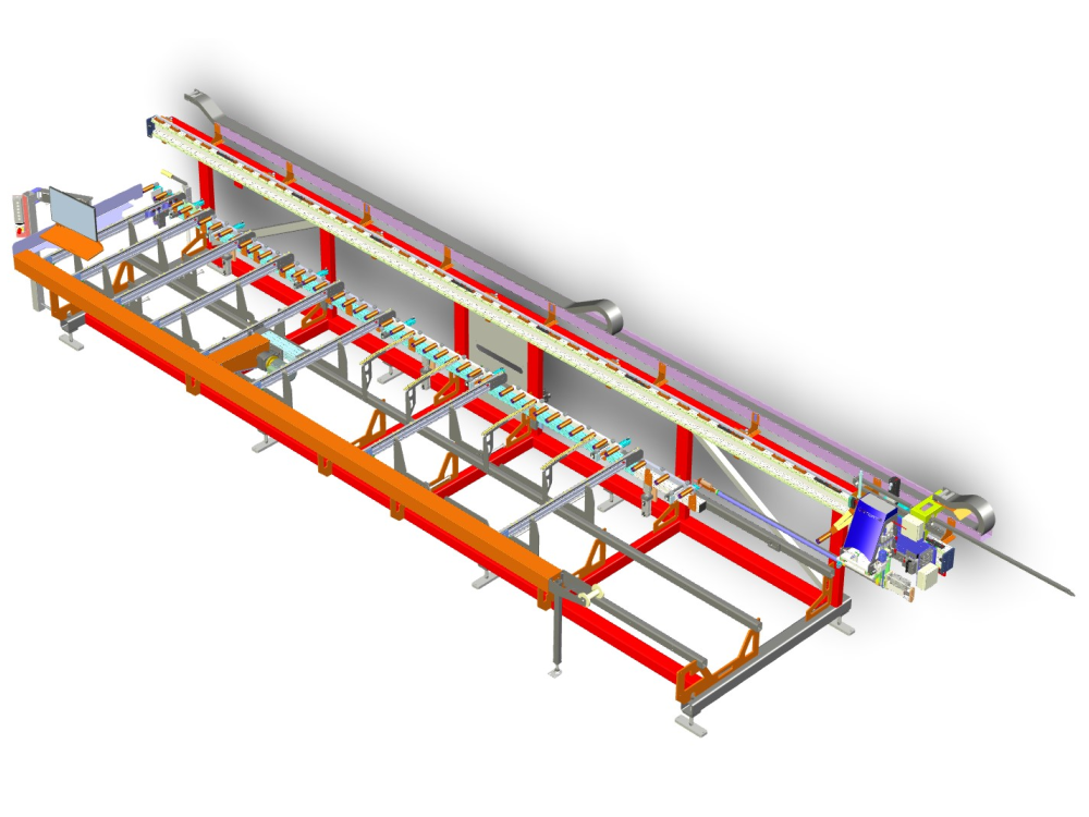
| + | |Main_Picture=Stuertz_Infeed_Table_Model.jpg | ||
| + | |Main_Picture_annotation={"version":"2.4.6","objects":[{"type":"image","version":"2.4.6","originX":"left","originY":"top","left":-23,"top":21,"width":1498,"height":931,"fill":"rgb(0,0,0)","stroke":null,"strokeWidth":0,"strokeDashArray":null,"strokeLineCap":"butt","strokeDashOffset":0,"strokeLineJoin":"miter","strokeMiterLimit":4,"scaleX":0.42,"scaleY":0.42,"angle":0,"flipX":false,"flipY":false,"opacity":1,"shadow":null,"visible":true,"clipTo":null,"backgroundColor":"","fillRule":"nonzero","paintFirst":"fill","globalCompositeOperation":"source-over","transformMatrix":null,"skewX":0,"skewY":0,"crossOrigin":"","cropX":0,"cropY":0,"src":"https://stuga.dokit.app/images/6/61/Stuertz_Infeed_Table_Model.jpg","filters":[]}],"height":450.16574585635357,"width":600} | ||
|Description=<translate>Critical measurements and settings for an Autoflow infeed table</translate> | |Description=<translate>Critical measurements and settings for an Autoflow infeed table</translate> | ||
|Categories=Software | |Categories=Software | ||
| Ligne 5 : | Ligne 7 : | ||
<translate><br /> | <translate><br /> | ||
| − | = Method = | + | =Method= |
{{Warning|...Make sure the GX axis is scaled correctly before starting any measurements}}{{Warning|...Ensure the infeed is set at the correct distance from the machining centre (500mm between feet centreline}}<br /> | {{Warning|...Make sure the GX axis is scaled correctly before starting any measurements}}{{Warning|...Ensure the infeed is set at the correct distance from the machining centre (500mm between feet centreline}}<br /> | ||
| − | * Use the gripper arm as the measuring stick. The datum must be set so that zero is the spindle centreline. | + | *Use the gripper arm as the measuring stick. The datum must be set so that zero is the spindle centreline. |
| − | * The measure point is when the gripper nose switch is depressed | + | *The measure point is when the gripper nose switch is depressed |
{| class="wikitable" | {| class="wikitable" | ||
| Ligne 19 : | Ligne 21 : | ||
|- | |- | ||
|Machining Centre to Infeed spacing | |Machining Centre to Infeed spacing | ||
| − | | | + | |Distance between centrelines of feet |
|500 | |500 | ||
| | | | ||
| Ligne 35 : | Ligne 37 : | ||
|- | |- | ||
|infeedToZeroX | |infeedToZeroX | ||
| − | |Distance from zero to profile load fence | + | |Distance from zero to profile load fence (profile side) |
| − | | | + | |615 |
| + | | | ||
| + | |- | ||
| + | |measureSensorPos1 | ||
| + | measureSensorPos2 | ||
| + | |Distance of gripper nose (depressed) to offcut measure sensors | ||
| + | Sensor 1 nearest MH | ||
| + | |1460 | ||
| + | 1480 | ||
| | | | ||
|- | |- | ||
| Ligne 49 : | Ligne 59 : | ||
|GX Move After Datum | |GX Move After Datum | ||
|Ideally set to max profile length+infeedZeroToX+100{{Warning|...Must not exceed GX Max pos}} | |Ideally set to max profile length+infeedZeroToX+100{{Warning|...Must not exceed GX Max pos}} | ||
| − | |||
|6500+600+100 | |6500+600+100 | ||
=7200 | =7200 | ||
| + | | | ||
| + | |- | ||
| + | |stopCylinderToZeroX | ||
| + | |Distance from the spindle centreline to the stop cylinder | ||
| + | {{Warning|...This should always be less than infeedToZeroX}}<br /> | ||
| + | |585 | ||
| + | | | ||
| + | |- | ||
| + | |loadOffsetX | ||
| + | |Relative distance to move after measuring finished to allow gripper to clear end of bar. | ||
| + | This can be measured - end of gripper "swan neck" to measuring sensor | ||
| + | <br /> | ||
| + | |1580 | ||
| + | | | ||
| + | |- | ||
| + | |GX Minimum Position | ||
| + | |Absolute minimum position of GX | ||
| + | Goal is for gripper nose switch to at least reach saw blade | ||
| + | {{Warning|...Take care with clashing of the Gripper Froward clamp with the MH infeed clamp}} | ||
| + | Ensure the end rubber buffers are set to prevent a mechanical clash beween the | ||
| + | | -1040 | ||
| + | | | ||
| + | |- | ||
| + | |Infeed Horizontal side clamp positions | ||
| + | |These are set up in the clamp setup as the "GripPos" for OuA_P2BFOnx{{Info|...Note - bar end should be set to -9999, as this effectively disables the other end of the bar from influencing the clamp on/off cycle}}<br /> | ||
| + | |1-950 | ||
| + | 2-1480 | ||
| + | |||
| + | 3-2600 | ||
| + | |||
| + | 4-3700 | ||
| + | |||
| + | 5-4800 | ||
| + | |||
| + | 6-6300 | ||
| + | |||
| + | 7-7050 | ||
| + | | | ||
| + | |- | ||
| + | |GY Min Position | ||
| + | |Limited by the backfence clamping in the saw area | ||
| + | |10 | ||
| + | | | ||
| + | |- | ||
| + | |GY Max Position | ||
| + | | | ||
| + | |54 | ||
| + | | | ||
| + | |- | ||
| + | |GZ Min Position | ||
| + | |Gripper must not bottom out on the saw tables | ||
| + | |6 | ||
| + | | | ||
| + | |- | ||
| + | |GZ Max position | ||
| + | |{{Info|...GY and GZ min / max positions and gripper tooth height (PullGripperHeight) should also be set in the file c:\ddrive\draw.mul}} | ||
| + | |70 | ||
| | | | ||
|}</translate> | |}</translate> | ||
{{PageLang | {{PageLang | ||
| + | |Language=en | ||
|SourceLanguage=none | |SourceLanguage=none | ||
|IsTranslation=0 | |IsTranslation=0 | ||
| − | |||
}} | }} | ||
{{AddComments}} | {{AddComments}} | ||
Version actuelle datée du 27 février 2023 à 17:46
Critical measurements and settings for an Autoflow infeed table

Sommaire
Method
- Use the gripper arm as the measuring stick. The datum must be set so that zero is the spindle centreline.
- The measure point is when the gripper nose switch is depressed
| Measurement | Description | A2027 Value | Photo |
|---|---|---|---|
| Machining Centre to Infeed spacing | Distance between centrelines of feet | 500 | |
| Zero Datum | Centreline of spindles | 0 | |
| measureStartPosX | Measuring start position
Should be so that measure sensor is on machining centre side of the profile load fence |
-880 | |
| infeedToZeroX | Distance from zero to profile load fence (profile side) | 615 | |
| measureSensorPos1
measureSensorPos2 |
Distance of gripper nose (depressed) to offcut measure sensors
Sensor 1 nearest MH |
1460
1480 |
|
| GX Axis Max position | Maximum travel on GX Axis
After datum, press estop and manually move to end of travel Note the value and subtract 10mm |
7255 | |
| GX Move After Datum | Ideally set to max profile length+infeedZeroToX+100 | 6500+600+100
=7200 |
|
| stopCylinderToZeroX | Distance from the spindle centreline to the stop cylinder
|
585 | |
| loadOffsetX | Relative distance to move after measuring finished to allow gripper to clear end of bar.
This can be measured - end of gripper "swan neck" to measuring sensor
|
1580 | |
| GX Minimum Position | Absolute minimum position of GX
Goal is for gripper nose switch to at least reach saw blade Ensure the end rubber buffers are set to prevent a mechanical clash beween the |
-1040 | |
| Infeed Horizontal side clamp positions | These are set up in the clamp setup as the "GripPos" for OuA_P2BFOnx |
1-950
2-1480 3-2600 4-3700 5-4800 6-6300 7-7050 |
|
| GY Min Position | Limited by the backfence clamping in the saw area | 10 | |
| GY Max Position | 54 | ||
| GZ Min Position | Gripper must not bottom out on the saw tables | 6 | |
| GZ Max position | 70 |
Draft
 Français
 English
 Deutsch
 Español
 Italiano
 Português