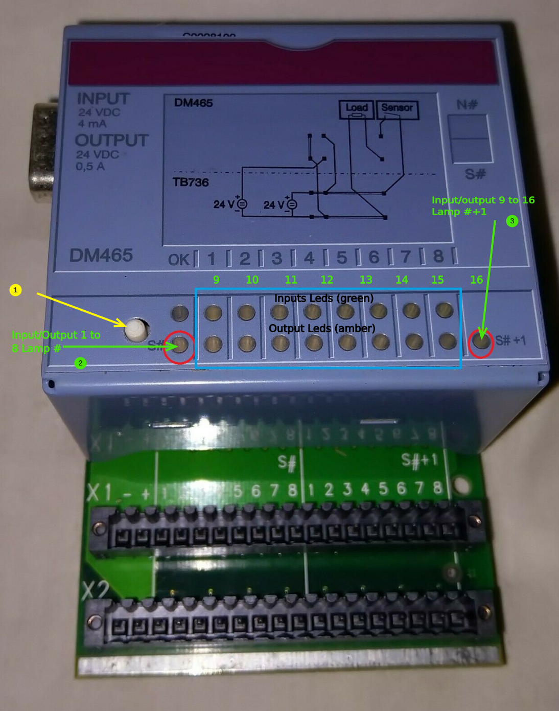
On the B&R plc you have 8 green led’s (inputs) and directly underneath these you have 8 yellow led’s (outputs).
There is a little white button on the PLC that you can press"1" ,when this is pressed a yellow led on the left hand side goes "2" out and a yellow one on the right "3"comes on.
When the left one"2" is ON you monitoring inputs X1 – X8 (left to right) on the green led’s and outputs Y1 – Y8 on the yellow led’s.
When the right one "3" is ON you monitoring inputs X9 – X16 (left to right) on the green led’s and outputs Y9 – Y16 on the yellow led’s.
So if the right yellow led is on and the third from left green led is on this input X11.
Here is a list of the I/O to help.
16 DIGITAL INPUTS
Slot Number:
Input No
Description:
Wire No>
Variable Name: (OLD WIRE NO>)
1
EMERGENCY STOP
X1
EM_STOP (wire 37)
2
BAR AT DOG 1 (MH)
X2
BAR1
3
BAR AT DOG 2
X3
BAR2
4
BAR AT DOG 3
X4
BAR3
5
BAR AT DOG 4
X5
BAR4
6
BAR AT DOG 5
X6
BAR5
7
BAR AT DOG 6
X7
BAR6
8
BAR AT SENSOR READY TO LIFT BAR INTO SAW
X8
BARSAW (wire 5)
9
BAR IN SAW (OUTPUT FROM SAW) RTA no.2 on I/O
X9
SAWLOADED (WIRE 26) y38
10
MOTOR CRANK FWD
X10
FORWARD_MOT
11
MOTOR CRANK AT HOME
X11
HOME_MOT
12
TABLE UP INPUT
X12
TABLE_UP
13
TABLE DOWN INPUTB
X13
TABLE_DWN
14
TABLE IN INPUT
X14
TABLE_IN
15
TABLE OUT INPUT
X15
TABLE_OUT
16
MATERIAL IN SAW INPUT
X16
? (WIRE 7)
16 DIGITAL OUTPUTS
Slot Number:
Output No.
Description
Wire No>
Variable Name: (OLD WIRE NO)
1
MOTOR GO FWD RELAY
Y1
MOTFWD
2
N/A
Y2
N/A
3
BAR 1 DOG VALVE
Y3
OUT_BAR1
4
BAR 2 VALVE
Y4
OUT_BAR2
5
BAR 3 VALVE
Y5
OUT_BAR3
6
BAR 4 VALVE
Y6
OUT_BAR4
7
BAR 5 VALVE
Y7
OUT_BAR5
8
BAR 6 VALVE
Y8
OUT_BAR6
9
OUTPUT TO MH (READY) RT_ACCEPCT
Y9
MHOUT (WIRE 21)
10
TABLE UP/DOWN VALVE
Y10
TABLEUD (WIRE 8)
11
TABLE IN/OUT VALVE
Y11
TABLEIO (WIRE 9)
12
LAMP 1 (24V LED MAYBE)
Y12
LAMP1
13
LAMP 2
Y13
LAMP2
14
LAMP 3
Y14
LAMP3
15
LAMP 4
Y15
LAMP4
16
OUTPUT TO SAW (BEEN LOADED)
Y16
BAR_IN_SAW (WIRE 36)
Another useful feature are the 4 lamps if the Lamps are wired in correctly “+ve goes to the gold leg of the led lamp”.
There is 4 led lamps on the outside of the transfer table box ,here is the faults that they report depending on status of the 4 lamps.
Internal PCC Variable:
Description / Operation:
FAULT1
EMERGENCY STOP
FAULT2
NA
FAULT3
MOTOR CRANK NOT HOME
FAULT4
MOTOR CRANK NOT OUT
FAULT5
SAW LOADER NOT DOWN
FAULT6
SAW LOADER NOT UP
FAULT7
SAW LOADER NOT IN
FAULT8
SAW LOADER NOT OUT
FAULT9
TBA
FAULT10
TBA
FAULT11
TBA
FAULT12
TBA
FAULT13
TBA
FAULT14
TBA
FAULT15
SAW NOT READY TO ACCEPT
LAMP1
LAMP2
LAMP3
LAMP4
FAULT NUMBER
OFF
OFF
OFF
OFF
0
ON
OFF
OFF
OFF
1
OFF
ON
OFF
OFF
2
ON
ON
OFF
OFF
3
OFF
OFF
ON
OFF
4
ON
OFF
ON
OFF
5
OFF
ON
ON
OFF
6
ON
ON
ON
OFF
7
OFF
OFF
OFF
ON
8
ON
OFF
OFF
ON
9
OFF
ON
OFF
ON
10
ON
ON
OFF
ON
11
OFF
OFF
ON
ON
12
ON
OFF
ON
ON
13
OFF
ON
ON
ON
14
ennone0
Commentaires
Draft
×
Erreur de saisie dans le nom du tutoriel
Vous avez entré un nom de page invalide, avec un ou plusieurs caractères suivants :
< > @ ~ : * € £ ` + = / \ | [ ] { } ; ? #
Connexion
Pas encore enregistré ? Créez un compte pour profiter de toutes les fonctionnalités du service !

 Français
 English
 Deutsch
 Español
 Italiano
 Português