| [version en cours de rédaction] | [version en cours de rédaction] |
| Ligne 6 : | Ligne 6 : | ||
|Tags=449, file, batch | |Tags=449, file, batch | ||
}} | }} | ||
| − | <translate>= Saw / Machining Centre Cutting List File Format = | + | <translate>=Saw / Machining Centre Cutting List File Format= |
| − | == 1. File Format == | + | ==1. File Format== |
The file is ASCII and consists of various types of records. Each starts with an identifying letter and ends with CR, LF. The fields are separated by a comma. The contents depends on the record type. | The file is ASCII and consists of various types of records. Each starts with an identifying letter and ends with CR, LF. The fields are separated by a comma. The contents depends on the record type. | ||
| Ligne 158 : | Ligne 158 : | ||
| width="64" valign="top" |3N | | width="64" valign="top" |3N | ||
| width="151" valign="top" |0 | | width="151" valign="top" |0 | ||
| − | | width="322" valign="top" |} | + | | width="322" valign="top" | } |
|- | |- | ||
| width="134" valign="top" |Param 2 | | width="134" valign="top" |Param 2 | ||
| width="64" valign="top" |3N | | width="64" valign="top" |3N | ||
| width="151" valign="top" |0 | | width="151" valign="top" |0 | ||
| − | | width="322" valign="top" |} Currently unused | + | | width="322" valign="top" | } Currently unused |
|- | |- | ||
| width="134" valign="top" |Param 3 | | width="134" valign="top" |Param 3 | ||
| width="64" valign="top" |3N | | width="64" valign="top" |3N | ||
| width="151" valign="top" |0 | | width="151" valign="top" |0 | ||
| − | | width="322" valign="top" |} | + | | width="322" valign="top" | } |
|- | |- | ||
| width="134" valign="top" |'''<u>Remainder Record</u>''' | | width="134" valign="top" |'''<u>Remainder Record</u>''' | ||
| Ligne 238 : | Ligne 238 : | ||
Records that are not required may be ignored. | Records that are not required may be ignored. | ||
| + | |||
| Ligne 258 : | Ligne 259 : | ||
The above file illustrates loading a single bar of 6000 mm, cutting 4 pieces, one of which has 4 operation lines - 2 drain entry slots, 2 drain exit slots and an espag prep in the middle. An offcut of 4176mm is stored. | The above file illustrates loading a single bar of 6000 mm, cutting 4 pieces, one of which has 4 operation lines - 2 drain entry slots, 2 drain exit slots and an espag prep in the middle. An offcut of 4176mm is stored. | ||
| − | == 2. Profile Orientation == | + | ==2. Profile Orientation== |
All profiles follow these rules: | All profiles follow these rules: | ||
<br /> | <br /> | ||
| − | * Large face always goes to the bottom, outside of frame to rear | + | *Large face always goes to the bottom, outside of frame to rear |
| − | * Eurogroove always goes to the rear | + | *Eurogroove always goes to the rear |
| − | * Leg on Z sashes / transoms always at bottom | + | *Leg on Z sashes / transoms always at bottom |
{{#annotatedImageLight:Fichier:Stuga Batch Cutting List Profile Orientation.png|0=1094px|hash=|jsondata=|mediaClass=Image|type=frameless|align=center|src=https://stuga.dokit.app/images/5/54/Stuga_Batch_Cutting_List_Profile_Orientation.png|href=./Fichier:Stuga Batch Cutting List Profile Orientation.png|resource=./Fichier:Stuga Batch Cutting List Profile Orientation.png|caption=|size=1094px}}{{Pin|...The operation position should always be given from the left hand end.}}{{#annotatedImageLight:Fichier:Stuga Batch Cutting List Operation Position.png|0=1094px|hash=|jsondata=|mediaClass=Image|type=frameless|align=center|src=https://stuga.dokit.app/images/b/b1/Stuga_Batch_Cutting_List_Operation_Position.png|href=./Fichier:Stuga Batch Cutting List Operation Position.png|resource=./Fichier:Stuga Batch Cutting List Operation Position.png|caption=|size=1094px}}<br /> | {{#annotatedImageLight:Fichier:Stuga Batch Cutting List Profile Orientation.png|0=1094px|hash=|jsondata=|mediaClass=Image|type=frameless|align=center|src=https://stuga.dokit.app/images/5/54/Stuga_Batch_Cutting_List_Profile_Orientation.png|href=./Fichier:Stuga Batch Cutting List Profile Orientation.png|resource=./Fichier:Stuga Batch Cutting List Profile Orientation.png|caption=|size=1094px}}{{Pin|...The operation position should always be given from the left hand end.}}{{#annotatedImageLight:Fichier:Stuga Batch Cutting List Operation Position.png|0=1094px|hash=|jsondata=|mediaClass=Image|type=frameless|align=center|src=https://stuga.dokit.app/images/b/b1/Stuga_Batch_Cutting_List_Operation_Position.png|href=./Fichier:Stuga Batch Cutting List Operation Position.png|resource=./Fichier:Stuga Batch Cutting List Operation Position.png|caption=|size=1094px}}<br /> | ||
| − | == 3. Operations == | + | ==3. Operations== |
The machining centre has a very flexible method for programming operations. The operations take the form of a CNC program stored on the machining centre. The programs are referred to by a tooling code. An operation can be as simple as a spot for a friction stay or as complicated as a 5 point door lock prep. The window designing package simply has to output the tooling code and the position along the bar. The machining centre handles all the profile related positional and size information. Each operation has a standard start position. The list of tooling codes for a particular system will be supplied to the window design software company by Stuga at least two months before the machine installation date. Certain standards are used to name the tooling codes. | The machining centre has a very flexible method for programming operations. The operations take the form of a CNC program stored on the machining centre. The programs are referred to by a tooling code. An operation can be as simple as a spot for a friction stay or as complicated as a 5 point door lock prep. The window designing package simply has to output the tooling code and the position along the bar. The machining centre handles all the profile related positional and size information. Each operation has a standard start position. The list of tooling codes for a particular system will be supplied to the window design software company by Stuga at least two months before the machine installation date. Certain standards are used to name the tooling codes. | ||
| − | === 3.1 Drainage === | + | ===3.1 Drainage=== |
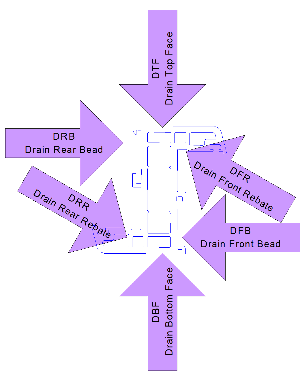
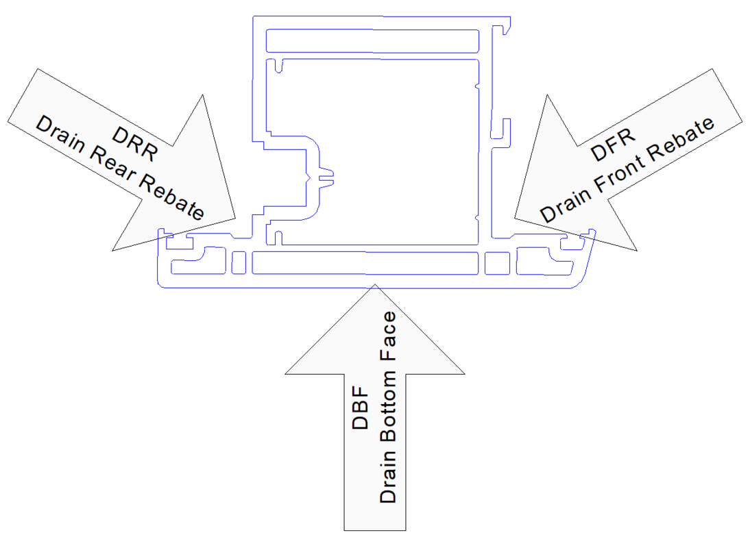
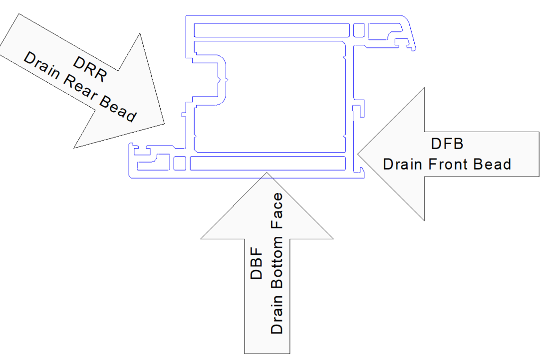
The tool codes for the drainage operations are the same for every profile. Each profile will have up to six different types of drainage. | The tool codes for the drainage operations are the same for every profile. Each profile will have up to six different types of drainage. | ||
<br /> | <br /> | ||
| Ligne 295 : | Ligne 296 : | ||
| width="84" valign="top" |DBF | | width="84" valign="top" |DBF | ||
|} | |} | ||
| + | |||
3.1.1 Outer Frame{{#annotatedImageLight:Fichier:Stuga Batch Cutting List Specification Outer Drainage.png|0=917px|hash=|jsondata=|mediaClass=Image|type=frameless|align=center|src=https://stuga.dokit.app/images/d/d2/Stuga_Batch_Cutting_List_Specification_Outer_Drainage.png|href=./Fichier:Stuga Batch Cutting List Specification Outer Drainage.png|resource=./Fichier:Stuga Batch Cutting List Specification Outer Drainage.png|caption=|size=917px}} | 3.1.1 Outer Frame{{#annotatedImageLight:Fichier:Stuga Batch Cutting List Specification Outer Drainage.png|0=917px|hash=|jsondata=|mediaClass=Image|type=frameless|align=center|src=https://stuga.dokit.app/images/d/d2/Stuga_Batch_Cutting_List_Specification_Outer_Drainage.png|href=./Fichier:Stuga Batch Cutting List Specification Outer Drainage.png|resource=./Fichier:Stuga Batch Cutting List Specification Outer Drainage.png|caption=|size=917px}} | ||
| + | |||
3.1.2 T Transom{{#annotatedImageLight:Fichier:Stuga Batch Cutting List Specification Transom Drainage.png|0=736px|hash=|jsondata=|mediaClass=Image|type=frameless|align=center|src=https://stuga.dokit.app/images/3/3d/Stuga_Batch_Cutting_List_Specification_Transom_Drainage.png|href=./Fichier:Stuga Batch Cutting List Specification Transom Drainage.png|resource=./Fichier:Stuga Batch Cutting List Specification Transom Drainage.png|caption=|size=736px}} | 3.1.2 T Transom{{#annotatedImageLight:Fichier:Stuga Batch Cutting List Specification Transom Drainage.png|0=736px|hash=|jsondata=|mediaClass=Image|type=frameless|align=center|src=https://stuga.dokit.app/images/3/3d/Stuga_Batch_Cutting_List_Specification_Transom_Drainage.png|href=./Fichier:Stuga Batch Cutting List Specification Transom Drainage.png|resource=./Fichier:Stuga Batch Cutting List Specification Transom Drainage.png|caption=|size=736px}} | ||
| + | |||
3.1.3 Z Transom{{#annotatedImageLight:Fichier:Stuga Batch Cutting List Specification Z Transom Drainage.png|0=1054px|hash=|jsondata=|mediaClass=Image|type=frameless|align=center|src=https://stuga.dokit.app/images/7/7f/Stuga_Batch_Cutting_List_Specification_Z_Transom_Drainage.png|href=./Fichier:Stuga Batch Cutting List Specification Z Transom Drainage.png|resource=./Fichier:Stuga Batch Cutting List Specification Z Transom Drainage.png|caption=|size=1054px}} | 3.1.3 Z Transom{{#annotatedImageLight:Fichier:Stuga Batch Cutting List Specification Z Transom Drainage.png|0=1054px|hash=|jsondata=|mediaClass=Image|type=frameless|align=center|src=https://stuga.dokit.app/images/7/7f/Stuga_Batch_Cutting_List_Specification_Z_Transom_Drainage.png|href=./Fichier:Stuga Batch Cutting List Specification Z Transom Drainage.png|resource=./Fichier:Stuga Batch Cutting List Specification Z Transom Drainage.png|caption=|size=1054px}} | ||
| + | |||
3.1.4 T Sash{{#annotatedImageLight:Fichier:Stuga Batch Cutting List Specification T Sash Drainage.png|0=1094px|hash=|jsondata=|mediaClass=Image|type=frameless|align=center|src=https://stuga.dokit.app/images/e/e9/Stuga_Batch_Cutting_List_Specification_T_Sash_Drainage.png|href=./Fichier:Stuga Batch Cutting List Specification T Sash Drainage.png|resource=./Fichier:Stuga Batch Cutting List Specification T Sash Drainage.png|caption=|size=1094px}} | 3.1.4 T Sash{{#annotatedImageLight:Fichier:Stuga Batch Cutting List Specification T Sash Drainage.png|0=1094px|hash=|jsondata=|mediaClass=Image|type=frameless|align=center|src=https://stuga.dokit.app/images/e/e9/Stuga_Batch_Cutting_List_Specification_T_Sash_Drainage.png|href=./Fichier:Stuga Batch Cutting List Specification T Sash Drainage.png|resource=./Fichier:Stuga Batch Cutting List Specification T Sash Drainage.png|caption=|size=1094px}} | ||
| + | |||
| Ligne 316 : | Ligne 322 : | ||
The start position of drain operations is the leading side of the drain slot as it enters the machine. This makes calculating the operation position a little more difficult, but it allows the slot to be cut in one pass, greatly increasing the efficiency of the Flowline. | The start position of drain operations is the leading side of the drain slot as it enters the machine. This makes calculating the operation position a little more difficult, but it allows the slot to be cut in one pass, greatly increasing the efficiency of the Flowline. | ||
| − | === 3.2 Espags === | + | ===3.2 Espags=== |
The espag prep is normally done in one operation. As a company normally has one espag and one shootbolt hardware on each profile, the tooling codes are normally: | The espag prep is normally done in one operation. As a company normally has one espag and one shootbolt hardware on each profile, the tooling codes are normally: | ||
| Ligne 328 : | Ligne 334 : | ||
<br /> | <br /> | ||
| − | === 3.3 Trickle Vents === | + | ===3.3 Trickle Vents=== |
Each vent hardware will have a different tooling code. The start position is in the centre of the operation. | Each vent hardware will have a different tooling code. The start position is in the centre of the operation. | ||
| − | === 3.4 Door Handles / Gearboxes === | + | ===3.4 Door Handles / Gearboxes=== |
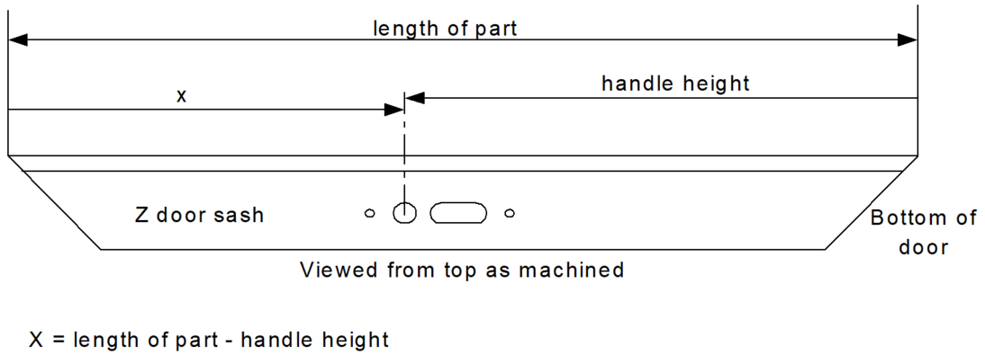
The door handle prep including gearboxes is done in one operation. The start position is the spindle centerline. | The door handle prep including gearboxes is done in one operation. The start position is the spindle centerline. | ||
For each distinct door lock there are two tooling codes for the two possible directions that the operation can face. There are four possible door formats (open in / open out coupled with left hand or right hand hung) which can be made with the two tooling codes. It will depend on the profile type as well as the door orientation as to which direction an operation will face. | For each distinct door lock there are two tooling codes for the two possible directions that the operation can face. There are four possible door formats (open in / open out coupled with left hand or right hand hung) which can be made with the two tooling codes. It will depend on the profile type as well as the door orientation as to which direction an operation will face. | ||
| + | |||
| Ligne 350 : | Ligne 357 : | ||
eg tooling code will be doorN | eg tooling code will be doorN | ||
| − | === 3.5 Door Keep Preps === | + | ===3.5 Door Keep Preps=== |
As with the doors, the door keeps are machined in one whole operation. For each pair of door preps there will be an equivalent pair of keep preps (if required) | As with the doors, the door keeps are machined in one whole operation. For each pair of door preps there will be an equivalent pair of keep preps (if required) | ||
| − | === 3.6 V Notches and Y Notches === | + | ===3.6 V Notches and Y Notches=== |
V Notches are classed as operations and have a standard code. Y notches are the half of a V notch added to the end of a reverse butt prep to give the full V notch when welded. | V Notches are classed as operations and have a standard code. Y notches are the half of a V notch added to the end of a reverse butt prep to give the full V notch when welded. | ||
| Ligne 369 : | Ligne 376 : | ||
|- | |- | ||
| width="241" valign="top" |Full V notch in front | | width="241" valign="top" |Full V notch in front | ||
| − | |||
| width="96" valign="top" |VFnnn | | width="96" valign="top" |VFnnn | ||
| Ligne 375 : | Ligne 381 : | ||
|- | |- | ||
| width="241" valign="top" |Full V notch in rear | | width="241" valign="top" |Full V notch in rear | ||
| − | |||
| width="96" valign="top" |VRnnn | | width="96" valign="top" |VRnnn | ||
| Ligne 381 : | Ligne 386 : | ||
|- | |- | ||
| width="241" valign="top" |Y notch in front right | | width="241" valign="top" |Y notch in front right | ||
| − | |||
| width="96" valign="top" |YFRnnn | | width="96" valign="top" |YFRnnn | ||
| Ligne 387 : | Ligne 391 : | ||
|- | |- | ||
| width="241" valign="top" |Y notch in front left | | width="241" valign="top" |Y notch in front left | ||
| − | |||
| width="96" valign="top" |YFLnnn | | width="96" valign="top" |YFLnnn | ||
| Ligne 393 : | Ligne 396 : | ||
|- | |- | ||
| width="241" valign="top" |Y notch in rear right | | width="241" valign="top" |Y notch in rear right | ||
| − | |||
| width="96" valign="top" |YRRnnn | | width="96" valign="top" |YRRnnn | ||
| Ligne 399 : | Ligne 401 : | ||
|- | |- | ||
| width="241" valign="top" |Y notch in rear left | | width="241" valign="top" |Y notch in rear left | ||
| − | |||
| width="96" valign="top" |YRLnnn | | width="96" valign="top" |YRLnnn | ||
| Ligne 411 : | Ligne 412 : | ||
Points to note: | Points to note: | ||
| − | * The Stuga Flowline has two separate blades that can be worked independently. A Y notch prep can be placed anywhere on a piece without interference to the adjacent piece. | + | *The Stuga Flowline has two separate blades that can be worked independently. A Y notch prep can be placed anywhere on a piece without interference to the adjacent piece. |
| − | * The ZX5 has 2 blades that work simultaneously to create a V notch. Y notches are made on the sawing side | + | *The ZX5 has 2 blades that work simultaneously to create a V notch. Y notches are made on the sawing side |
| − | === 3.7 Other Operations === | + | ===3.7 Other Operations=== |
The Flowline is capable of an unlimited number of other operations. These can take the form of spot preps, hinge preps, casement keeps, door packers, hinge bolts, etc. These will be defined for each installation. | The Flowline is capable of an unlimited number of other operations. These can take the form of spot preps, hinge preps, casement keeps, door packers, hinge bolts, etc. These will be defined for each installation. | ||
| − | == 4. Bar Usage == | + | ==4. Bar Usage== |
The Stuga Flowline optimises the batch for use of profile automatically as standard. The Stuga sawing centre has optimising as an optional extra. If optimising is not installed, the following rules should be followed to optimise the batch before cutting. | The Stuga Flowline optimises the batch for use of profile automatically as standard. The Stuga sawing centre has optimising as an optional extra. If optimising is not installed, the following rules should be followed to optimise the batch before cutting. | ||
| − | === 4.1. Trim Cut === | + | ===4.1. Trim Cut=== |
The saw allows a trim cut at the beginning of the bar. It is adjustable from the 'Machine Parameters' option.- For more information see the operating manual. It is usually set to 10 mm to allow for inconsistent length and squareness of profile available from the manufacturer. | The saw allows a trim cut at the beginning of the bar. It is adjustable from the 'Machine Parameters' option.- For more information see the operating manual. It is usually set to 10 mm to allow for inconsistent length and squareness of profile available from the manufacturer. | ||
| − | === 4.2. Piece to Piece gap === | + | ===4.2. Piece to Piece gap=== |
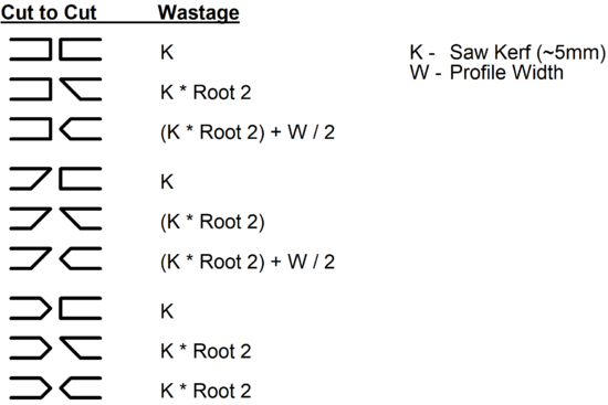
The machine keeps the gap in between pieces as small as possible (equal to the kerf). Because of the way cuts are made, however, some piece to piece gaps are larger. The following table lists the piece gaps, for reference when programming optimisation packages.{{#annotatedImageLight:Fichier:Stuga Batch Cutting List Specification Gaps.png|0=550px|hash=|jsondata=|mediaClass=Image|type=frameless|align=center|src=https://stuga.dokit.app/images/3/32/Stuga_Batch_Cutting_List_Specification_Gaps.png|href=./Fichier:Stuga Batch Cutting List Specification Gaps.png|resource=./Fichier:Stuga Batch Cutting List Specification Gaps.png|caption=|size=550px}} | The machine keeps the gap in between pieces as small as possible (equal to the kerf). Because of the way cuts are made, however, some piece to piece gaps are larger. The following table lists the piece gaps, for reference when programming optimisation packages.{{#annotatedImageLight:Fichier:Stuga Batch Cutting List Specification Gaps.png|0=550px|hash=|jsondata=|mediaClass=Image|type=frameless|align=center|src=https://stuga.dokit.app/images/3/32/Stuga_Batch_Cutting_List_Specification_Gaps.png|href=./Fichier:Stuga Batch Cutting List Specification Gaps.png|resource=./Fichier:Stuga Batch Cutting List Specification Gaps.png|caption=|size=550px}} | ||
| Ligne 429 : | Ligne 430 : | ||
As the table shows, it is most economical to avoid arrow head cuts on the left-hand side of the cut length, except when cutting another arrow-head. | As the table shows, it is most economical to avoid arrow head cuts on the left-hand side of the cut length, except when cutting another arrow-head. | ||
| − | == 5. Printer File Format == | + | ==5. Printer File Format== |
For customers who require extra information on the labels, the link should be set up to generate a separate printer file. This file provides a reference for a label format for each piece in a batch of windows. | For customers who require extra information on the labels, the link should be set up to generate a separate printer file. This file provides a reference for a label format for each piece in a batch of windows. | ||
| − | === 5.1 Structure === | + | ===5.1 Structure=== |
The file is ASCII text: | The file is ASCII text: | ||
<br /><syntaxhighlight> | <br /><syntaxhighlight> | ||
| Ligne 443 : | Ligne 444 : | ||
</syntaxhighlight>The batch record is written at the start of the batch and contains general header information exactly like the cutting list. Piece records are written exactly as the cutting list. Label records contain the bare text for printing onto the label. There can be up to 8 Label records per piece. | </syntaxhighlight>The batch record is written at the start of the batch and contains general header information exactly like the cutting list. Piece records are written exactly as the cutting list. Label records contain the bare text for printing onto the label. There can be up to 8 Label records per piece. | ||
| − | === 5.2 Format === | + | ===5.2 Format=== |
{| class="wikitable" border="0" cellspacing="0" cellpadding="0" | {| class="wikitable" border="0" cellspacing="0" cellpadding="0" | ||
| width="134" valign="top" |'''Field''' | | width="134" valign="top" |'''Field''' | ||
| Ligne 551 : | Ligne 552 : | ||
The file name output by software supplier will be “bbbbbbbb.prn” where “bbbbbbbb” is the batch number. Note that the batch number should match the batch number of the cutting list. | The file name output by software supplier will be “bbbbbbbb.prn” where “bbbbbbbb” is the batch number. Note that the batch number should match the batch number of the cutting list. | ||
| + | |||
| Ligne 588 : | Ligne 590 : | ||
X, Reinforcing: 1000 CRS | X, Reinforcing: 1000 CRS | ||
</syntaxhighlight> | </syntaxhighlight> | ||
| − | </translate> | + | |
| + | = 6. Reiniforcing Field = | ||
| + | Addition - June 2022 | ||
| + | |||
| + | Requirement is for a field to determine if reinforcing is used in order to sort the cut pieces into two sections. | ||
| + | |||
| + | Given the assumption that "Zeb" label printing will be active (ie the 3rd party software company outputs the label data), this will mean that the id field is not required for "important" data. Therefore additianal data can be added to signify the reinforcing type used. | ||
| + | |||
| + | |||
| + | T | ||
| + | <br /></translate> | ||
{{PageLang | {{PageLang | ||
|Language=en | |Language=en | ||
Version du 16 juin 2022 à 07:58
Full specification of the file format used by the entire range of Stuga machinery for cutting lengths and machining operations
Saw / Machining Centre Cutting List File Format
1. File Format
The file is ASCII and consists of various types of records. Each starts with an identifying letter and ends with CR, LF. The fields are separated by a comma. The contents depends on the record type.
Structure
Batch record {
    Load records {
        Piece records {
            Operations records {
            }
        }
    Remainder record
}
The batch record is written at the start of the batch and contains general header information. Load records are written whenever stock details change; they contain all information required to load the correct stock. Piece records contain sawing information and other details relevant to each cut piece. Operation lines are written where there is additional machining work to be carried out, e.g. drilling, notching, routing. There may be many operation lines per piece.
| Field | Format | Example | Notes |
| Batch Record | |||
| Record Type | 1A | B | |
| Batch No | 8A | 12JN9101 | Specified in computer |
| Status | 1A | S | Manufacturing stage |
| Load Record | |||
| Record Type | 1A | L | |
| Stock No | 10A | AB1000 | Profile stock number |
| Colour | 5A | WHITE | Profile colour |
| Pairing | N | 1 | 1 = single, 2 = pair (singles only) |
| Length | 5N | 60000 | Stock Length |
| Quantity | 3N | 012 | Number of pairs or singles to load |
| Piece Record | |||
| Record Type | 1A | P | |
| Length | 5N | 10000 | Cut length |
| Sawcut | 2A | <> | Two of | [ ] \ / < > |
| Trolley No | 2N | 02 | Trolley Number |
| Slot No | 2N | 17 | Position on trolley |
| Identification | 40A | ASD100/001/F^A1 | Job / Item / Position in window |
| Cut Angle L | 4N | 0900 | Angle at left end |
| Cut Angle R | 4N | 0900 | Angle at right end |
| Piece No | 12N | 000000000112 | Unique piece number. Should start a 1 for the first piece in the batch and increment up. |
| Operation Record | |||
| Record Type | 1A | O | |
| Position | 5N | 02340 | Distance from start of piece |
| Tooling Code | 8A | DFR | Operation name |
| Param 1 | 3N | 0 | } |
| Param 2 | 3N | 0 | } Currently unused |
| Param 3 | 3N | 0 | } |
| Remainder Record | |||
| Record Type | 1A | R | |
| Length | 5N | 00100 | Length of offcut |
| Sawcut | 2A | || | Cut type if req. |
| Destination | 1A | W | W = Waste, S = Store |
| Piece No | 12N | 000000000000 | Unique piece no |
Format Notes
a) All lengths are in tenths of mm.
b) Angles in tenths of a degree
c) Pieces are included, even if there are no operations
d) Numeric fields have leading zeros. Alphanumeric fields are left justified an padded with spaces.
e) The Piece No is used for tracking. It cross-references with the number printed on a label. This can be input by a user or scanned with a bar-code reader.
f) If pair cutting, there will still be one record per piece. The identification numbers still have to be carried, and there may be operations to carry out.
g) There will be one (two for pairs) remainder records per bar, even if the length is zero.
h) The parameters for operation lines depend on the type of operation.
i) To minimise wastage, alternating from arrowhead to square cuts should be avoided.
File Name
The file name output by software supplier will be “bbbbbbbb.449” where “bbbbbbbb” is the batch number. Note that the batch number should be read from the batch record.
Programming Notes
To allow for future enhancements, any program reading this file should follow these guidelines.
a) Allow for possibility of more than one batch record, allowing batch records to be concatenated.
b) Allow fields to be of variable length.
c) Ignore any extra fields.
d) If the saw cannot cut arbitrary angles, the angle to cut may be obtained from the ‘Saw Cut’ field.
Records that are not required may be ignored.
Example File
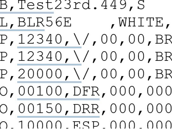
B,Test23rd.449,S
L,BLR56E   ,WHITE,1,60000,001
P,12340,\/,00,00,BR129A/001/F_A1     ,0450,0450,000000002685
P,12340,\/,00,00,BR129A/001/F_A1     ,0450,0450,000000002686
P,20000,\/,00,00,BR129A/001/F_A1     ,0450,0450,000000002687
O,00100,DFR,000,000,000
O,00150,DRR,000,000,000
O,10000,ESP,000,000,000
O,19830,DRR,000,000,000
O,19880,DFR,000,000,000
P,20000,\/,00,00,BR129A/001/F_A1     ,0450,0450,000000002688
R,47160,[],S,100000000437
The above file illustrates loading a single bar of 6000 mm, cutting 4 pieces, one of which has 4 operation lines - 2 drain entry slots, 2 drain exit slots and an espag prep in the middle. An offcut of 4176mm is stored.
2. Profile Orientation
All profiles follow these rules:
- Large face always goes to the bottom, outside of frame to rear
- Eurogroove always goes to the rear
- Leg on Z sashes / transoms always at bottom
3. Operations
The machining centre has a very flexible method for programming operations. The operations take the form of a CNC program stored on the machining centre. The programs are referred to by a tooling code. An operation can be as simple as a spot for a friction stay or as complicated as a 5 point door lock prep. The window designing package simply has to output the tooling code and the position along the bar. The machining centre handles all the profile related positional and size information. Each operation has a standard start position. The list of tooling codes for a particular system will be supplied to the window design software company by Stuga at least two months before the machine installation date. Certain standards are used to name the tooling codes.
3.1 Drainage
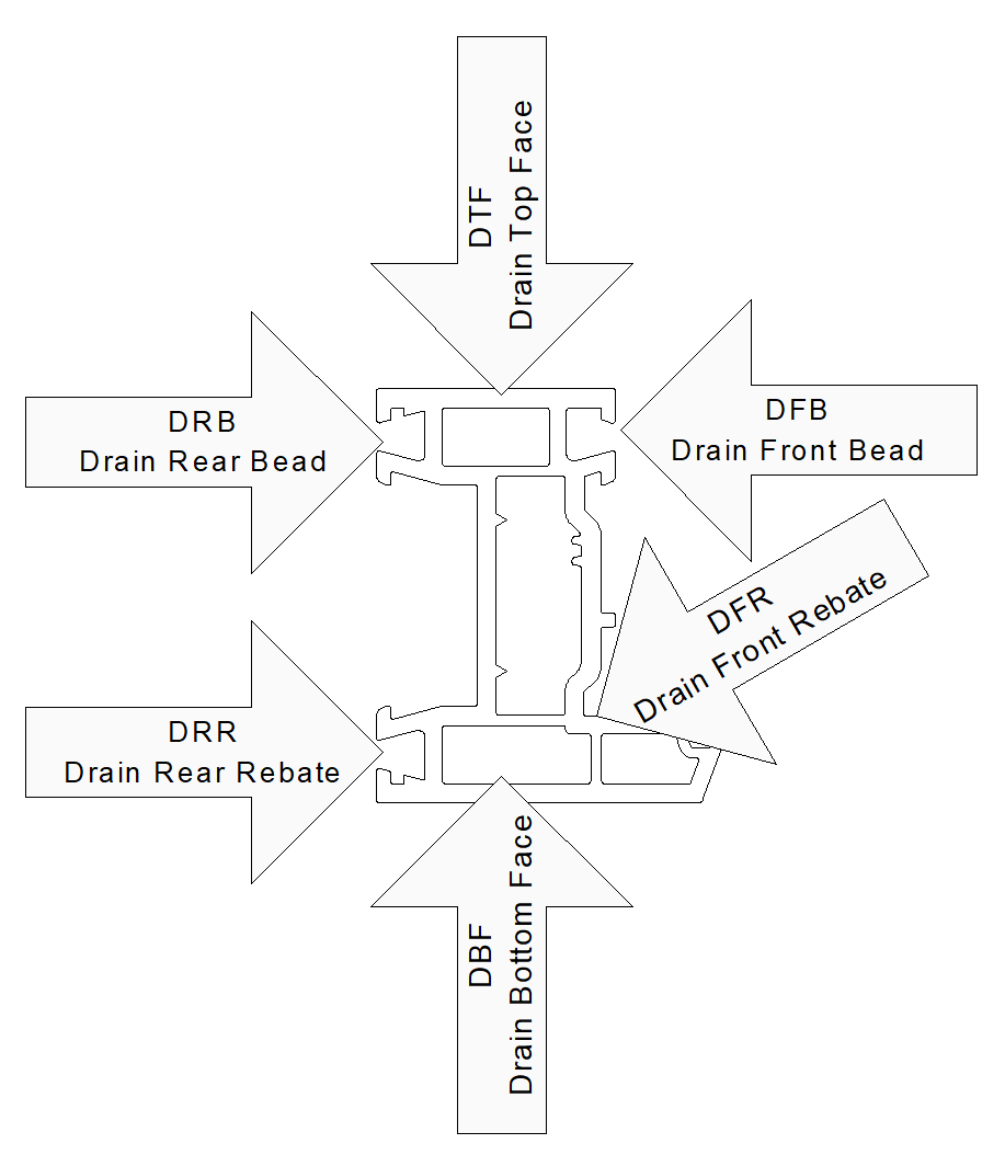
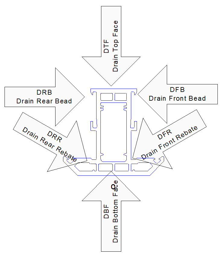
The tool codes for the drainage operations are the same for every profile. Each profile will have up to six different types of drainage.
| Drainage Type | Tool Code |
| Drain Front Rebate | DFB |
| Drain Rear Rebate | DRR |
| Drain Front Bead | DFB |
| Drain Rear Bead | DRB |
| Drain Top Face | DTF |
| Drain Bottom Face | DBF |
3.1.1 Outer Frame
3.1.2 T Transom
3.1.3 Z Transom
3.1.4 T Sash
3.1.5 Z Sash
The start position of drain operations is the leading side of the drain slot as it enters the machine. This makes calculating the operation position a little more difficult, but it allows the slot to be cut in one pass, greatly increasing the efficiency of the Flowline.
3.2 Espags
The espag prep is normally done in one operation. As a company normally has one espag and one shootbolt hardware on each profile, the tooling codes are normally:
ESP - Espag
SHB - Shootbolt
The start position of the operation is the centre of the prep.
3.3 Trickle Vents
Each vent hardware will have a different tooling code. The start position is in the centre of the operation.
3.4 Door Handles / Gearboxes
The door handle prep including gearboxes is done in one operation. The start position is the spindle centerline.
For each distinct door lock there are two tooling codes for the two possible directions that the operation can face. There are four possible door formats (open in / open out coupled with left hand or right hand hung) which can be made with the two tooling codes. It will depend on the profile type as well as the door orientation as to which direction an operation will face.
Use a P suffix for ‘positive’ doors and the distance to the handle centerline will be measured as
eg tooling code will be doorP
Use an N suffix for ‘negative’ doors and the distance to the handle centerline will be measured as is
eg tooling code will be doorN
3.5 Door Keep Preps
As with the doors, the door keeps are machined in one whole operation. For each pair of door preps there will be an equivalent pair of keep preps (if required)
3.6 V Notches and Y Notches
V Notches are classed as operations and have a standard code. Y notches are the half of a V notch added to the end of a reverse butt prep to give the full V notch when welded.
Format:
NotchCode followed by depth of notch in 10ths mm
Notch Codes
| Description | Code | View from top |
| Full V notch in front | VFnnn | |
| Full V notch in rear | VRnnn | |
| Y notch in front right | YFRnnn | |
| Y notch in front left | YFLnnn | |
| Y notch in rear right | YRRnnn | |
| Y notch in rear left | YRLnnn |
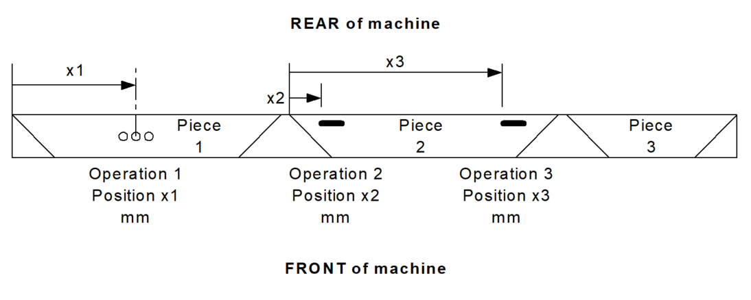
The position should be given to the point of the notch from the loading end (ie left-hand end in above diagrams). This will mean that Y notches will either have a position of zero or (part length).
Points to note:
- The Stuga Flowline has two separate blades that can be worked independently. A Y notch prep can be placed anywhere on a piece without interference to the adjacent piece.
- The ZX5 has 2 blades that work simultaneously to create a V notch. Y notches are made on the sawing side
3.7 Other Operations
The Flowline is capable of an unlimited number of other operations. These can take the form of spot preps, hinge preps, casement keeps, door packers, hinge bolts, etc. These will be defined for each installation.
4. Bar Usage
The Stuga Flowline optimises the batch for use of profile automatically as standard. The Stuga sawing centre has optimising as an optional extra. If optimising is not installed, the following rules should be followed to optimise the batch before cutting.
4.1. Trim Cut
The saw allows a trim cut at the beginning of the bar. It is adjustable from the 'Machine Parameters' option.- For more information see the operating manual. It is usually set to 10 mm to allow for inconsistent length and squareness of profile available from the manufacturer.
4.2. Piece to Piece gap
The machine keeps the gap in between pieces as small as possible (equal to the kerf). Because of the way cuts are made, however, some piece to piece gaps are larger. The following table lists the piece gaps, for reference when programming optimisation packages.
As the table shows, it is most economical to avoid arrow head cuts on the left-hand side of the cut length, except when cutting another arrow-head.
5. Printer File Format
For customers who require extra information on the labels, the link should be set up to generate a separate printer file. This file provides a reference for a label format for each piece in a batch of windows.
5.1 Structure
The file is ASCII text:
Batch record {
    Piece records {
        Label records {
        }
    }
}
The batch record is written at the start of the batch and contains general header information exactly like the cutting list. Piece records are written exactly as the cutting list. Label records contain the bare text for printing onto the label. There can be up to 8 Label records per piece.
5.2 Format
| Field | Format | Example | Notes |
| Batch Record | |||
| Record Type | 1A | B | |
| Batch No | 8A | 12JN9101 | Specified in computer |
| Status | 1A | S | Manufacturing stage |
| Piece Record | |||
| Record Type | 1A | P | |
| Length | 5N | 10000 | Cut length |
| Sawcut | 2A | <> | Two of | [ ] \ / < > |
| Trolley No | 2N | 02 | Trolley Number |
| Slot No | 2N | 17 | Position on trolley |
| Identification | 40A | ASD100/001/F^A1 | Job / Item / Position in window |
| Cut Angle L | 4N | 0900 | Angle at left end |
| Cut Angle R | 4N | 0900 | Angle at right end |
| Piece No | 12N | 000000000112 | Unique piece number |
| Label Record | |||
| Record Type | 1A | X | |
| Label Text | 80N | Any ASCII text | Text will be printed line by line |
Format Notes
a) All lengths are in tenths of mm.
b) Angles in tenths of a degree
c) Numeric fields have leading zeros. Alphanumeric fields are left justified an padded with spaces.
d) The Piece No is used for tracking. It cross-references with the piece number from the cutting list.
File Name
The file name output by software supplier will be “bbbbbbbb.prn” where “bbbbbbbb” is the batch number. Note that the batch number should match the batch number of the cutting list.
Example File
B,00001256.prn,S
P,12340,\/,00,01,BR129A/001/F_A1     ,0450,0450,000000000001
X,    Customer: Mrs Jones
X,    Location: Lounge
X,        ------------------------------------------
X,        \               0906 mm                  /
X,         \                                      /
X,         --------------------------------------
X,                                 Reinforcing: None
P,12340,\/,00,02,BR129A/001/F_A1     ,0450,0450,000000000002
X,    Customer: Mrs Jones
X,    Location: Lounge
X,       ------------------------------------------
X,        \               1206 mm                  /
X,         \                                      /
X,         --------------------------------------
X,                                 Reinforcing: 1000 CRS
P,20000,\/,00,02,BR129A/001/F_A1     ,0450,0450,000000000003
X,    Customer: Mrs Jones
X,    Location: Lounge
X,        ------------------------------------------
X,        \               0906 mm                  /
X,         \                                      /
X,         --------------------------------------
X,                                 Reinforcing: None
P,20000,\/,00,08,BR129A/001/F_A1     ,0450,0450,000000000004
X,    Customer: Mrs Jones
X,    Location: Lounge
X,       ------------------------------------------
X,        \               1206 mm                  /
X,         \                                      /
X,         --------------------------------------
X,                                 Reinforcing: 1000 CRS
6. Reiniforcing Field
Addition - June 2022
Requirement is for a field to determine if reinforcing is used in order to sort the cut pieces into two sections.
Given the assumption that "Zeb" label printing will be active (ie the 3rd party software company outputs the label data), this will mean that the id field is not required for "important" data. Therefore additianal data can be added to signify the reinforcing type used.
T
Draft



 Français
 English
 Deutsch
 Español
 Italiano
 Português