|
|
| (Une révision intermédiaire par le même utilisateur non affichée) |
| Ligne 9 : |
Ligne 9 : |
| | }} | | }} |
| | {{Introduction | | {{Introduction |
| − | |Introduction=<translate><u>'''Tools Required'''</u> | + | |Introduction=<translate>15/09/2025 |
| | | | |
| | | | |
| − | Standard screwdriver set
| + | Moved to Confluance |
| − |
| |
| − | Standard grease gun and cartridge
| |
| | | | |
| | | | |
| − | | + | Click [https://stuga-ltd.atlassian.net/wiki/external/YTRmMjYyZjA3MGVmNDYzMDk1ZDdlNTM0Y2VlMzk0Y2Q Here]</translate> |
| − | <u>'''Parts Required'''</u>
| |
| − | | |
| − | | |
| − | Mains air connection</translate>
| |
| | }} | | }} |
| | {{Materials}} | | {{Materials}} |
| | {{EPI}} | | {{EPI}} |
| | {{Tuto Step | | {{Tuto Step |
| − | |Step_Title=<translate>Caution</translate> | + | |Step_Title=<translate></translate> |
| − | |Step_Content=<translate>Output testing will be carried out under a no-emergency stop situation | + | |Step_Content=<translate></translate> |
| − | | |
| − | | |
| − | ensure pcl coupling is used for ability for quick disconnection
| |
| − | | |
| − | | |
| − | Ensure all colleagues are aware of testing and ensure good working practise is followed</translate>
| |
| − | |Step_Picture_00=R0015338_Bench_Assemble_Serial_Plate_caution.png
| |
| − | }}
| |
| − | {{Tuto Step
| |
| − | |Step_Title=<translate>Blank Spare ports</translate>
| |
| − | |Step_Content=<translate>Blank off all unused bulkhead and connection ports not required</translate>
| |
| − | |Step_Picture_00=R0015338_Bench_Assemble_Serial_Plate_caution.png
| |
| − | }}
| |
| − | {{Tuto Step
| |
| − | |Step_Title=<translate>Lubrication</translate>
| |
| − | |Step_Content=<translate>All lubrication points should be greased prior to testing
| |
| − | | |
| − | | |
| − | ensure the following are greased
| |
| − | | |
| − | | |
| − | '''<u>Leadscrews</u>'''
| |
| − | | |
| − | Z axis leadscrew 2off leadscrews 1 off grease point per leadscrew
| |
| − | | |
| − | Y Axis Leadscrew 1 off grease point
| |
| − | | |
| − | VZ axis leadscrew 1 off grease point
| |
| − | | |
| − | '''<u>Bearings</u>'''
| |
| − | | |
| − | 4 off Y axis bearings
| |
| − | | |
| − | 4 off Z axis bearings
| |
| − | | |
| − | 8 off VZ axis bearings
| |
| − | | |
| − | | |
| − | | |
| − | <br /></translate>
| |
| − | |Step_Picture_00=R0015320_Pneumatic_Output_Test_Screenshot_2023-11-06_113551.png
| |
| − | }}
| |
| − | {{Tuto Step
| |
| − | |Step_Title=<translate>Connect air to Air service unit</translate>
| |
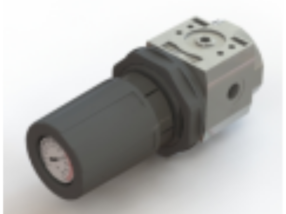
| − | |Step_Content=<translate>Ensure soft start adjuster is fully wound out
| |
| − | | |
| − | | |
| − | Set air service unit to 6 bar
| |
| − | | |
| − | <br /></translate>
| |
| − | |Step_Picture_00=R0015114_Bench_Assemble_Valve_Banks_and_Regulators_Screenshot_2023-11-02_073451.png
| |
| − | }}
| |
| − | {{Tuto Step
| |
| − | |Step_Title=<translate>Check Red Permanent feed line Air Gun</translate>
| |
| − | |Step_Content=<translate>Check for audible leaks and correct if required
| |
| − | | |
| − | | |
| − | Check operation of air gun . Ensure pressure is set to maximum of 2 bar</translate>
| |
| − | |Step_Picture_00=R0015338_Bench_Assemble_Serial_Plate_caution.png
| |
| − | }}
| |
| − | {{Tuto Step
| |
| − | |Step_Title=<translate>Check Red permanent feed Z axis</translate>
| |
| − | |Step_Content=<translate>Set Z axis support pressure. Set at 5 bar, and adjust to balance. Rotary ring should be held in position under cylinder pressure, but be able able to be moved up and down by turning the leadscrew by hand
| |
| − | | |
| − | If resistance is felt or axis bounces when leadscrew is turned , check air connections for correct piping</translate>
| |
| − | |Step_Picture_00=R0015114_Bench_Assemble_Valve_Banks_and_Regulators_Screenshot_2023-11-02_074048.png
| |
| − | }}
| |
| − | {{Tuto Step
| |
| − | |Step_Title=<translate>Check Red permanent feed VZ axis</translate>
| |
| − | |Step_Content=<translate>Set VZ axis regulator to 5 bar</translate>
| |
| − | |Step_Picture_00=R0015114_Bench_Assemble_Valve_Banks_and_Regulators_Screenshot_2023-11-02_074048.png
| |
| − | }}
| |
| − | {{Tuto Step
| |
| − | |Step_Title=<translate>Manual over Ride air service unit</translate>
| |
| − | |Step_Content=<translate>Manually override air service unit to purge Blue ring main
| |
| − | | |
| − | | |
| − | Caution All cylinders should move to their home positions
| |
| − | | |
| − | | |
| − | Check for audible leaks from ring main and cylinder connections
| |
| − | | |
| − | | |
| − | Check for leaks when all outputs are individually fire also</translate>
| |
| − | |Step_Picture_00=R0015338_Bench_Assemble_Serial_Plate_caution.png
| |
| − | }}
| |
| − | {{Tuto Step
| |
| − | |Step_Title=<translate>Test Y269 Ring blow</translate>
| |
| − | |Step_Content=<translate>Home position Blower should be switched off
| |
| − | | |
| − | | |
| − | Fire valve, blower should activate on tool break sensor assembly
| |
| − | | |
| − | | |
| − | Check orientation of in line flow regulator . Fully closed, air feed should stop totally . If not possible, flow regulator is fitted incorrectly</translate>
| |
| − | |Step_Picture_00=R0015320_Pneumatic_Output_Test_Screenshot_2023-11-02_085644.png
| |
| − | }}
| |
| − | {{Tuto Step
| |
| − | |Step_Title=<translate>Y270 Clamp hold</translate>
| |
| − | |Step_Content=<translate>Home position is retracted away from bottom rollers
| |
| − | | |
| − | | |
| − | Manually fire valve, cylinder should move toward datum rollers</translate>
| |
| − | |Step_Picture_00=R0015320_Pneumatic_Output_Test_Screenshot_2023-11-02_085644.png
| |
| − | }}
| |
| − | {{Tuto Step
| |
| − | |Step_Title=<translate>Y350 Infeed top clamp</translate>
| |
| − | |Step_Content=<translate>Home position should be lifted up
| |
| − | | |
| − | | |
| − | Manually fire valve, set regulator pressure to 2 bar
| |
| − | | |
| − | | |
| − | Clamp should move down when fired</translate>
| |
| − | |Step_Picture_00=R0015320_Pneumatic_Output_Test_Screenshot_2023-11-02_085644.png
| |
| − | }}
| |
| − | {{Tuto Step
| |
| − | |Step_Title=<translate>Y351 Infeed side clamp</translate>
| |
| − | |Step_Content=<translate>Home position should be retracted away from datum rollers
| |
| − | | |
| − | | |
| − | Manually fire valve, set regulator pressure to 2 bar
| |
| − | | |
| − | | |
| − | Clamp should move in when fired</translate>
| |
| − | |Step_Picture_00=R0015320_Pneumatic_Output_Test_Screenshot_2023-11-02_085644.png
| |
| − | }}
| |
| − | {{Tuto Step
| |
| − | |Step_Title=<translate>Y360 work blowers</translate>
| |
| − | |Step_Content=<translate>Home position Blower should be switched off
| |
| − | | |
| − | | |
| − | Fire valve, blower should activate on infeed datum roller assembly
| |
| − | | |
| − | | |
| − | Check orientation of in line flow regulator . Fully closed, air feed should stop totally . If not possible, flow regulator is fitted incorrectly</translate>
| |
| − | |Step_Picture_00=R0015320_Pneumatic_Output_Test_Screenshot_2023-11-02_085644.png
| |
| − | }}
| |
| − | {{Tuto Step
| |
| − | |Step_Title=<translate>Y386 Clamps middle</translate>
| |
| − | |Step_Content=<translate>Shared Output for top and side clamp
| |
| − | | |
| − | | |
| − | Home positions are
| |
| − | | |
| − | | |
| − | side clamp retracted away from datum rollers
| |
| − | | |
| − | Top clamp retracted away from datum rollers
| |
| − | | |
| − | | |
| − | Manually fire valve
| |
| − | | |
| − | | |
| − | Set
| |
| − | | |
| − | Y386 side clamp regulator to 2 bar
| |
| − | | |
| − | Y386 top clamp regulator to 2 bar
| |
| − | | |
| − | | |
| − | Clamps should move towards datum rollers
| |
| − | | |
| − | <br /></translate>
| |
| − | |Step_Picture_00=R0015320_Pneumatic_Output_Test_Screenshot_2023-11-02_085644.png
| |
| − | }}
| |
| − | {{Tuto Step
| |
| − | |Step_Title=<translate>V389 V Cut output</translate>
| |
| − | |Step_Content=<translate>Ensure all clamps are clear from V notch cut axis
| |
| − | | |
| − | | |
| − | Home position should be up
| |
| − | | |
| − | | |
| − | Manually fire valve
| |
| − | | |
| − | | |
| − | V notch assembly should move down towards the floor</translate>
| |
| − | |Step_Picture_00=R0015320_Pneumatic_Output_Test_Screenshot_2023-11-02_085644.png
| |
| − | }}
| |
| − | {{Tuto Step
| |
| − | |Step_Title=<translate>Y395 V clamp</translate>
| |
| − | |Step_Content=<translate>Y395 is a shared output for V top and side clamp
| |
| − | | |
| − | | |
| − | Home positions are
| |
| − | | |
| − | | |
| − | side clamp retracted away from datum rollers
| |
| − | | |
| − | Top clamp retracted away from datum rollers
| |
| − | | |
| − | | |
| − | Manually fire valve
| |
| − | | |
| − | | |
| − | Set
| |
| − | | |
| − | | |
| − | Y395 side clamp regulator to 4 bar
| |
| − | | |
| − | Y395 top clamp regulator to 4 bar
| |
| − | | |
| − | | |
| − | Clamps should move towards datum rollers when fired</translate>
| |
| − | |Step_Picture_00=R0015320_Pneumatic_Output_Test_Screenshot_2023-11-02_085644.png
| |
| − | }}
| |
| − | {{Tuto Step
| |
| − | |Step_Title=<translate>Disconnect air</translate>
| |
| − | |Step_Content=<translate>Disconnect air and remove fitted blanks for testing</translate>
| |
| − | |Step_Picture_00=R0015114_Bench_Assemble_Valve_Banks_and_Regulators_Screenshot_2023-11-02_073451.png
| |
| | }} | | }} |
| | {{Notes}} | | {{Notes}} |

 Français
 English
 Deutsch
 Español
 Italiano
 Português