|
|
| (7 révisions intermédiaires par le même utilisateur non affichées) |
| Ligne 1 : |
Ligne 1 : |
| | {{Tuto Details | | {{Tuto Details |
| − | |Main_Picture=R0015114_Bench_Assemble_Valve_Banks_and_Regulators_Screenshot_2023-10-25_091222.png | + | |Main_Picture=R0015114_Bench_Assemble_Valve_Banks_and_Regulators_Screenshot_2024-03-13_133429.png |
| − | |Main_Picture_annotation={"version":"2.4.6","objects":[{"type":"image","version":"2.4.6","originX":"left","originY":"top","left":12,"top":-41,"width":821,"height":756,"fill":"rgb(0,0,0)","stroke":null,"strokeWidth":0,"strokeDashArray":null,"strokeLineCap":"butt","strokeDashOffset":0,"strokeLineJoin":"miter","strokeMiterLimit":4,"scaleX":0.71,"scaleY":0.71,"angle":0,"flipX":false,"flipY":false,"opacity":1,"shadow":null,"visible":true,"clipTo":null,"backgroundColor":"","fillRule":"nonzero","paintFirst":"fill","globalCompositeOperation":"source-over","transformMatrix":null,"skewX":0,"skewY":0,"crossOrigin":"","cropX":0,"cropY":0,"src":"https://stuga.dokit.app/images/7/7f/R0015114_Bench_Assemble_Valve_Banks_and_Regulators_Screenshot_2023-10-25_091222.png","filters":[]}],"height":449.7695852534562,"width":600} | + | |Main_Picture_annotation={"version":"2.4.6","objects":[{"type":"image","version":"2.4.6","originX":"left","originY":"top","left":-171,"top":-125,"width":449,"height":420,"fill":"rgb(0,0,0)","stroke":null,"strokeWidth":0,"strokeDashArray":null,"strokeLineCap":"butt","strokeDashOffset":0,"strokeLineJoin":"miter","strokeMiterLimit":4,"scaleX":2.07,"scaleY":2.07,"angle":0,"flipX":false,"flipY":false,"opacity":1,"shadow":null,"visible":true,"clipTo":null,"backgroundColor":"","fillRule":"nonzero","paintFirst":"fill","globalCompositeOperation":"source-over","transformMatrix":null,"skewX":0,"skewY":0,"crossOrigin":"","cropX":0,"cropY":0,"src":"https://stuga.dokit.app/images/3/30/R0015114_Bench_Assemble_Valve_Banks_and_Regulators_Screenshot_2024-03-13_133429.png","filters":[]}],"height":450,"width":600} |
| | |Description=<translate>Assembly details for pneumatic components</translate> | | |Description=<translate>Assembly details for pneumatic components</translate> |
| | |Categories=Production | | |Categories=Production |
| | |Difficulty=Medium | | |Difficulty=Medium |
| − | |Duration=1 | + | |Duration=2.5 |
| | |Duration-type=hour(s) | | |Duration-type=hour(s) |
| | }} | | }} |
| | {{Introduction | | {{Introduction |
| − | |Introduction=<translate>'''<u>Tools Required</u>''' | + | |Introduction=<translate>15/09/2025 |
| | | | |
| | | | |
| − | Standard hex key set
| + | Moved to Confluance |
| | | | |
| − | Standard spanner set
| |
| | | | |
| − | Standard HSS drill set
| + | Click [https://stuga-ltd.atlassian.net/wiki/external/OGM5MzI3NDQ3NDM0NGQxZThiMTEwNGExNTFlZGEzNzI Here]</translate> |
| − | | |
| − | Standard tap set
| |
| − | | |
| − | | |
| − | '''<u>Parts Required</u>'''
| |
| − | | |
| − | | |
| − | H0007998 Regulator internal mount 5 way x 1
| |
| − | | |
| − | P0000010 Elbow Adaptor 6mm - 1/8 BSPT (Taper thread) x 14
| |
| − | | |
| − | P0000020 Fitting: Plug 1/8" BSP (Grubscrew Type) x 9
| |
| − | | |
| − | P0000021 air gun assembly x 1
| |
| − | | |
| − | P0000024 hex nipple 1/4 x 3
| |
| − | | |
| − | P0000058 Regulator Mounting Kit x 1
| |
| − | | |
| − | P0000074 Elbow Adaptor 8mm - 1/8 BSP (Pneumax not acceptable) x 2
| |
| − | | |
| − | P0000096 Fitting: Brass Reducing Bush 1/2 - 1/4 x 2
| |
| − | | |
| − | P0000142 Elbow Adaptor 8mm - 1/8 BSP x 2
| |
| − | | |
| − | P0000145 tee equal 1/4 x 3
| |
| − | | |
| − | P0000159 Fitting: Stem Blanking Plug 6mm x 2
| |
| − | | |
| − | P0000277 Fitting: Bulkhead Female 8mm x 1/4 BSP x 1
| |
| − | | |
| − | P0000278 Regulator 0-2 bar x 1
| |
| − | | |
| − | P0000332 Regulator with Gauge G1/8<nowiki>''</nowiki> 0-8 bar x 8
| |
| − | | |
| − | P0000361 1/4<nowiki>'' Male Probe to suit 1/4''</nowiki> PCL Female coupling x 1
| |
| − | | |
| − | P0000419 Air Service Unit OH (P0283) x 1
| |
| − | | |
| − | P0001071 Valve base type41 8 position x 1
| |
| − | | |
| − | P0001074 Fitting: 1/4" BSP Hex Head Silencer x 4
| |
| − | | |
| − | P0001101 Male straight 1/4 bsp to 12mm x 1
| |
| − | | |
| − | P0001102 Fitting male elbow 12mm 1/4 x 4
| |
| − | | |
| − | P0001105 Bulkhead straight 12mm x 6
| |
| − | | |
| − | P0001186 Valve. 24v dc smc x 8
| |
| − | | |
| − | <br /></translate>
| |
| | }} | | }} |
| | {{Materials}} | | {{Materials}} |
| | {{EPI}} | | {{EPI}} |
| | {{Tuto Step | | {{Tuto Step |
| − | |Step_Title=<translate>Unless otherwise stated</translate> | + | |Step_Title=<translate></translate> |
| − | |Step_Content=<translate>Use Loctite 243 on all fasteners | + | |Step_Content=<translate></translate> |
| − | | |
| − | Use Loctite 572 on all threaded pneumatic connection
| |
| − | | |
| − | Pen mark all fasteners to show finalised</translate>
| |
| − | |Step_Picture_00=R0015086_Assemble_Pneumatics_on_to_electrical_cabinet_loctite_243.png
| |
| − | }}
| |
| − | {{Tuto Step
| |
| − | |Step_Title=<translate>Ecr raised</translate>
| |
| − | |Step_Content=<translate>Ecr raised to amend regulator bracket to remove redundant holes and add fixing holes for valve bank
| |
| − | | |
| − | | |
| − | Use part as is until process to update is complete
| |
| − | | |
| − | | |
| − | Drill regulator bracket M4 to suit valve base</translate>
| |
| − | |Step_Picture_00=R0015114_Bench_Assemble_Valve_Banks_and_Regulators_Screenshot_2023-10-25_091527.png
| |
| − | |Step_Picture_01=R0015114_Bench_Assemble_Valve_Banks_and_Regulators_Screenshot_2023-10-25_091518.png
| |
| − | }}
| |
| − | {{Tuto Step
| |
| − | |Step_Title=<translate>Assemble valve bank</translate>
| |
| − | |Step_Content=<translate>Assemble valve bank as shown</translate>
| |
| − | |Step_Picture_00=R0015114_Bench_Assemble_Valve_Banks_and_Regulators_Screenshot_2023-10-25_092337.png
| |
| − | |Step_Picture_01=R0015114_Bench_Assemble_Valve_Banks_and_Regulators_Screenshot_2023-10-25_092343.png
| |
| − | }}
| |
| − | {{Tuto Step
| |
| − | |Step_Title=<translate>Attach valve bank</translate>
| |
| − | |Step_Content=<translate>Attach valve bank to regulator bracket using M4 socket caps , washers and nyloc nuts</translate>
| |
| − | |Step_Picture_00=R0015114_Bench_Assemble_Valve_Banks_and_Regulators_Screenshot_2023-10-25_092741.png
| |
| − | }}
| |
| − | {{Tuto Step
| |
| − | |Step_Title=<translate>Assemble regulators</translate>
| |
| − | |Step_Content=<translate>Assemble 7 off regulators with 6mm elbows and spare port blanked
| |
| − | | |
| − | | |
| − | Assemble 1 off regulator with 8mm elbows and spare port blanked</translate>
| |
| − | |Step_Picture_00=R0015114_Bench_Assemble_Valve_Banks_and_Regulators_Screenshot_2023-10-25_092813.png
| |
| − | }}
| |
| − | {{Tuto Step
| |
| − | |Step_Title=<translate>Assemble Air service unit</translate>
| |
| − | |Step_Content=<translate>Assemble air service unit</translate>
| |
| − | |Step_Picture_00=R0015114_Bench_Assemble_Valve_Banks_and_Regulators_Screenshot_2023-11-02_073451.png
| |
| − | }}
| |
| − | {{Tuto Step
| |
| − | |Step_Title=<translate>Mount air service unit</translate>
| |
| − | |Step_Content=<translate>Mount air service unit to front lower panel</translate>
| |
| − | |Step_Picture_00=R0015114_Bench_Assemble_Valve_Banks_and_Regulators_Screenshot_2023-11-02_073613.png
| |
| − | }}
| |
| − | {{Tuto Step
| |
| − | |Step_Title=<translate>Mount regulators</translate>
| |
| − | |Step_Content=<translate>Mount regulators to front lower panel
| |
| − | | |
| − | | |
| − | As viewed from front, bottom right regulator should have 8mm fittings</translate>
| |
| − | |Step_Picture_00=R0015114_Bench_Assemble_Valve_Banks_and_Regulators_Screenshot_2023-11-02_073613.png
| |
| − | }}
| |
| − | {{Tuto Step
| |
| − | |Step_Title=<translate>Mount bulkheads</translate>
| |
| − | |Step_Content=<translate>Mount 3 off 12mm bulkheads to lower panel</translate>
| |
| − | |Step_Picture_00=R0015114_Bench_Assemble_Valve_Banks_and_Regulators_Screenshot_2023-11-02_073613.png
| |
| − | }}
| |
| − | {{Tuto Step
| |
| − | |Step_Title=<translate>Assemble and mount 0-2bar regulator</translate>
| |
| − | |Step_Content=<translate>Assemble and mount 0-2 bar regulator to lower front panel</translate>
| |
| − | |Step_Picture_00=R0015114_Bench_Assemble_Valve_Banks_and_Regulators_Screenshot_2023-11-02_073613.png
| |
| − | }}
| |
| − | {{Tuto Step
| |
| − | |Step_Title=<translate>Fit and connect air gun assembly</translate>
| |
| − | |Step_Content=<translate>Fit 8mm bulkhead to lower front panel
| |
| − | | |
| − | | |
| − | Fit air gun assembly
| |
| − | | |
| − | | |
| − | Connect 8mm red pipe from reg OUT to bulkhead</translate>
| |
| − | |Step_Picture_00=R0015114_Bench_Assemble_Valve_Banks_and_Regulators_Screenshot_2023-11-02_073825.png
| |
| − | }}
| |
| − | {{Tuto Step
| |
| − | |Step_Title=<translate>Fit cable gland</translate>
| |
| − | |Step_Content=<translate>Fit cable gland for air service unit</translate>
| |
| − | |Step_Picture_00=R0015114_Bench_Assemble_Valve_Banks_and_Regulators_Screenshot_2023-11-02_073451.png
| |
| − | }}
| |
| − | {{Tuto Step
| |
| − | |Step_Title=<translate>Fit labels for regulators</translate>
| |
| − | |Step_Content=<translate>Print and Attach labels for regulator's
| |
| − | | |
| − | | |
| − | Labels to be added both sides of panel
| |
| − | | |
| − | | |
| − | From top left to bottom right
| |
| − | | |
| − | | |
| − | Y350 Clamp Infeed Top
| |
| − | | |
| − | Y351 Clamp Infeed Side
| |
| − | | |
| − | Y386 Clamp Middle Top
| |
| − | | |
| − | Y386 Clamp middle Side
| |
| − | | |
| − | Y395 Clamp V Top
| |
| − | | |
| − | Y395 clamp V Side
| |
| − | | |
| − | Z Axis Support
| |
| − | | |
| − | VZ Axis Support</translate>
| |
| − | |Step_Picture_00=R0015114_Bench_Assemble_Valve_Banks_and_Regulators_Screenshot_2023-11-02_074048.png
| |
| − | }}
| |
| − | {{Tuto Step
| |
| − | |Step_Title=<translate>Lower rear panel bulklheads</translate>
| |
| − | |Step_Content=<translate>Fit 3 off 12mm bulkheads to rear lower panel</translate>
| |
| − | |Step_Picture_00=R0015114_Bench_Assemble_Valve_Banks_and_Regulators_Screenshot_2023-11-02_074155.png
| |
| − | }}
| |
| − | {{Tuto Step
| |
| − | |Step_Title=<translate>Label bulkheads</translate>
| |
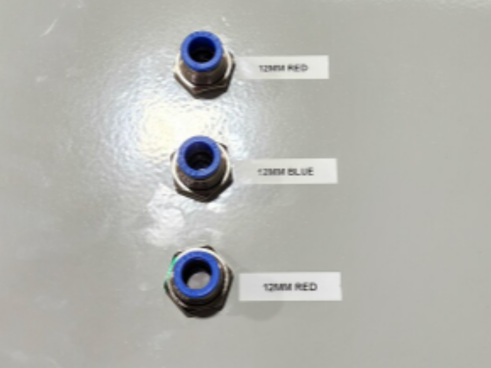
| − | |Step_Content=<translate>Print and fit Labels to identify bullheads as
| |
| − | | |
| − | | |
| − | 12mm red 2 off
| |
| − | | |
| − | 12mm blue 1 off</translate>
| |
| − | |Step_Picture_00=R0015114_Bench_Assemble_Valve_Banks_and_Regulators_Screenshot_2023-11-02_074155.png
| |
| | }} | | }} |
| | {{Notes}} | | {{Notes}} |

 Français
 English
 Deutsch
 Español
 Italiano
 Português