| [version en cours de rédaction] | [version en cours de rédaction] |
| Ligne 87 : | Ligne 87 : | ||
|Step_Picture_01=R0015335_Mount_Electrical_Cabinet_Screenshot_2023-11-16_134024.png | |Step_Picture_01=R0015335_Mount_Electrical_Cabinet_Screenshot_2023-11-16_134024.png | ||
|Step_Picture_02=R0015335_Mount_Electrical_Cabinet_Screenshot_2023-11-16_134046.png | |Step_Picture_02=R0015335_Mount_Electrical_Cabinet_Screenshot_2023-11-16_134046.png | ||
| + | }} | ||
| + | {{Tuto Step | ||
| + | |Step_Title=<translate>Check for ECR</translate> | ||
| + | |Step_Content=<translate>Drawing amendment ECR requested for side sheet panel | ||
| + | |||
| + | |||
| + | Check indicated hole is 12.5mm | ||
| + | |||
| + | |||
| + | If not rework</translate> | ||
| + | |Step_Picture_00=R0015335_Mount_Electrical_Cabinet_Screenshot_2025-01-09_084537.png | ||
| + | |Step_Picture_01=R0015335_Mount_Electrical_Cabinet_Screenshot_2025-01-09_084713.png | ||
}} | }} | ||
{{Tuto Step | {{Tuto Step | ||
Version actuelle datée du 9 janvier 2025 à 09:47
Details for mounting of electrical control panel
Sommaire
- 1 Introduction
- 2 Étape 1 - Unless otherwise stated
- 3 Étape 2 - Fit Trunking 1
- 4 Étape 3 - Cut Trunking 2
- 5 Étape 4 - Fit Air gun bracket
- 6 Étape 5 - Check for ECR
- 7 Étape 6 - Fit side sheet
- 8 Étape 7 - Fit trunking to side sheet
- 9 Étape 8 - Fit ethercat mount plate
- 10 Étape 9 - Fit Regulator bracket
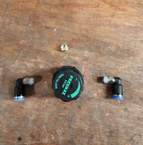
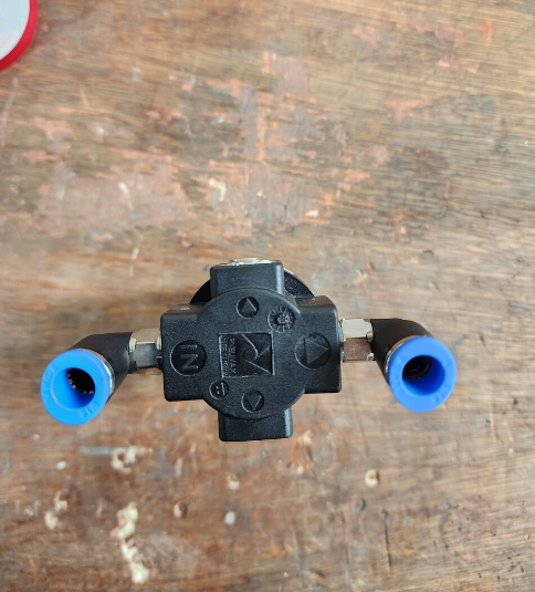
- 11 Étape 10 - Assemble air gun regulator
- 12 Étape 11 - Assemble air gun assembly
- 13 Étape 12 - Connect pipe
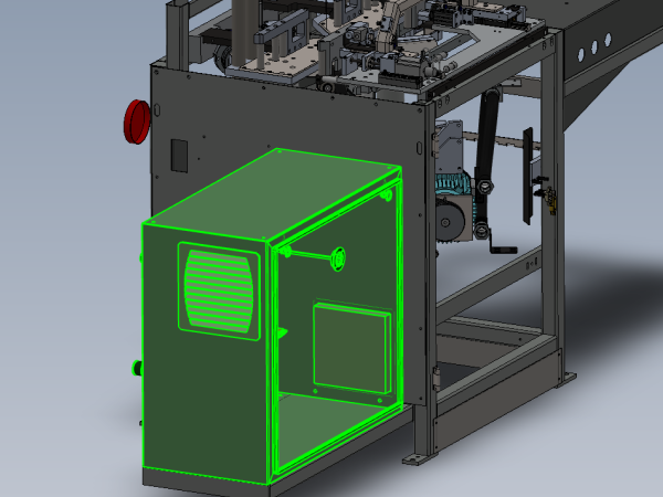
- 14 Étape 13 - Position Cabinet
- 15 Étape 14 - Fix cabinet
- 16 Commentaires
Introduction
Tools Required
Standard hex key set
Standard spanner set
Standard HSS drill set
Standard Tap set
Parts Required
D0004391E Left hand side sheet x 1 D0015425 Bracket: Beckhoff Box Right Angle x 1
D0015426 Mounting Plate: Airgun Assy x 1
D0015425 Beckhoff right angle mounting plate x 1
P0000020 Fitting: Plug 1/8" BSP (Grubscrew Type) x 1
P0000021 Airgun Assembly x 1
P0000142 Elbow Adaptor 8mm - 1/8 BSP x 2
P0000277 Fitting: Bulkhead Female 8mm x 1/4 BSP x 1
P0000278 Regulator 0-2 bar x 1
P0000373 Regulator fixing bracket x 1
R0015016C Electrical cabinet wiring Mod F
Étape 1 - Unless otherwise stated
All bolts to have Loctite 243 adhesive applied unless otherwise stated
All Threaded Pneumatic connections to have Loctite 570 applied
All bolts to be pen marked once adhesive applied and correct tension added
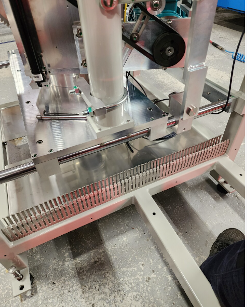
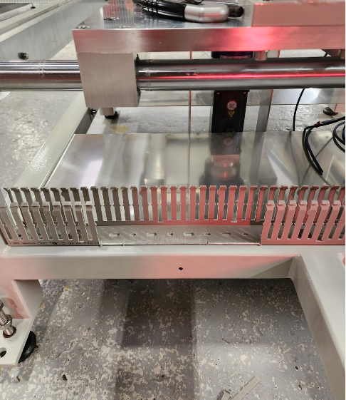
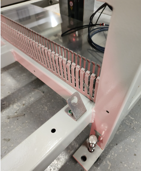
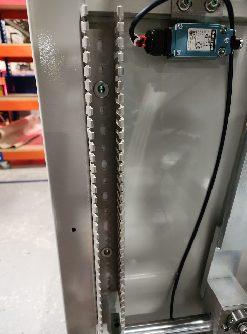
Étape 2 - Fit Trunking 1
1 Fit 1 length of trunking as shown. Fix with M5 x 10 button sockets and penny washers
Remove sections shown to align with cutout on side sheet
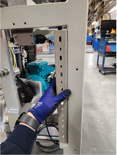
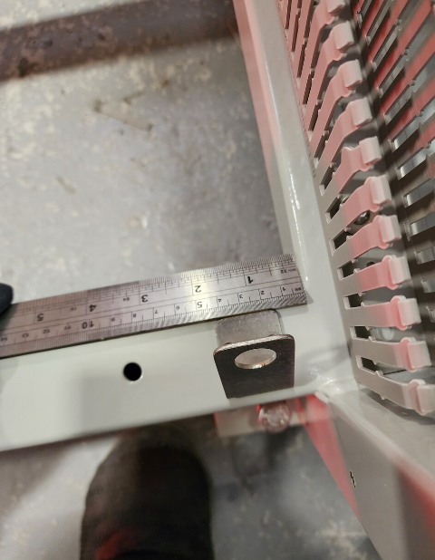
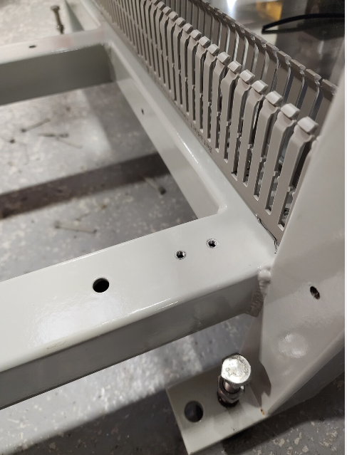
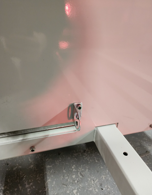
Étape 4 - Fit Air gun bracket
Mark and drill 2 off M5 tapped holes to suit air gun bracket .
Position 15mm as shown from edge of frame
Fix with 2 off M5 x 12 socket caps and M5 motor plate washer
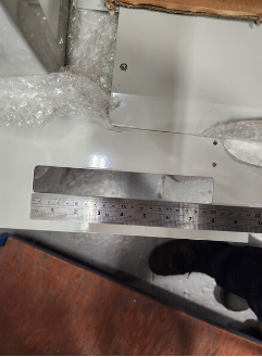
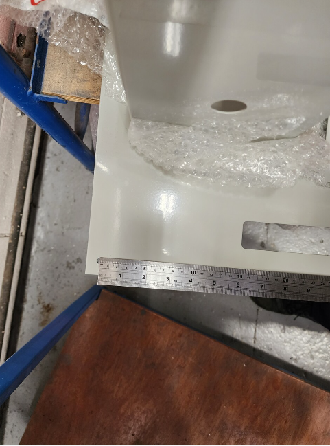
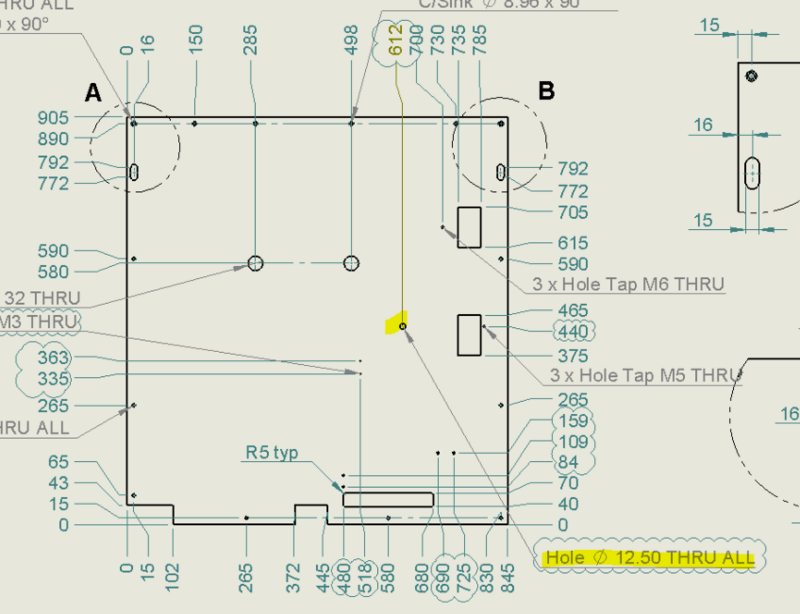
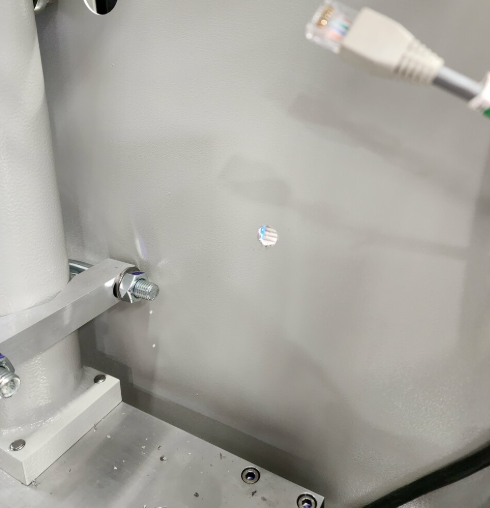
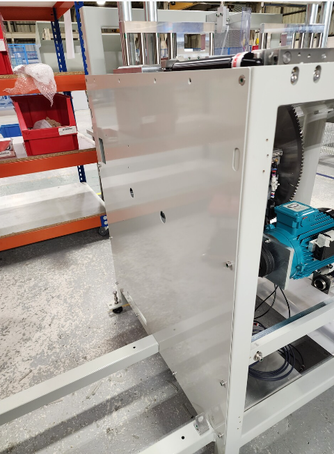
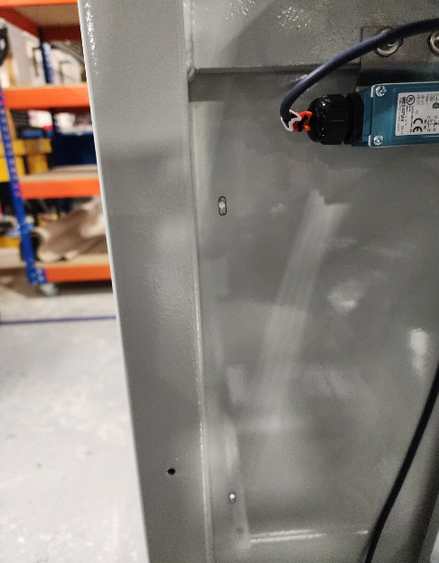
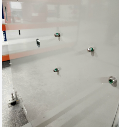
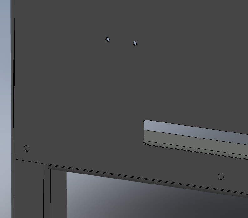
Étape 5 - Check for ECR
Drawing amendment ECR requested for side sheet panel
Check indicated hole is 12.5mm
If not rework
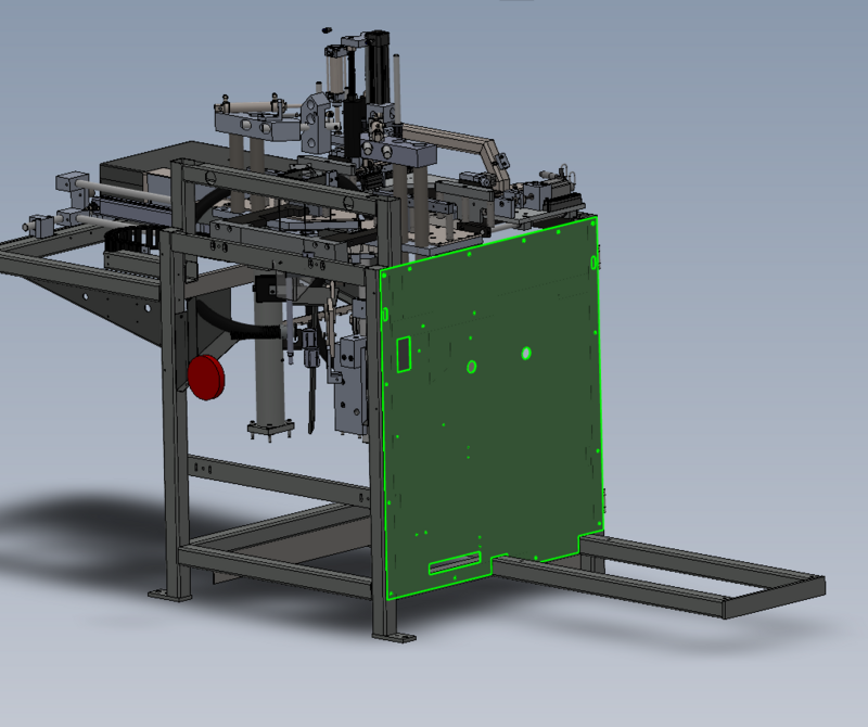
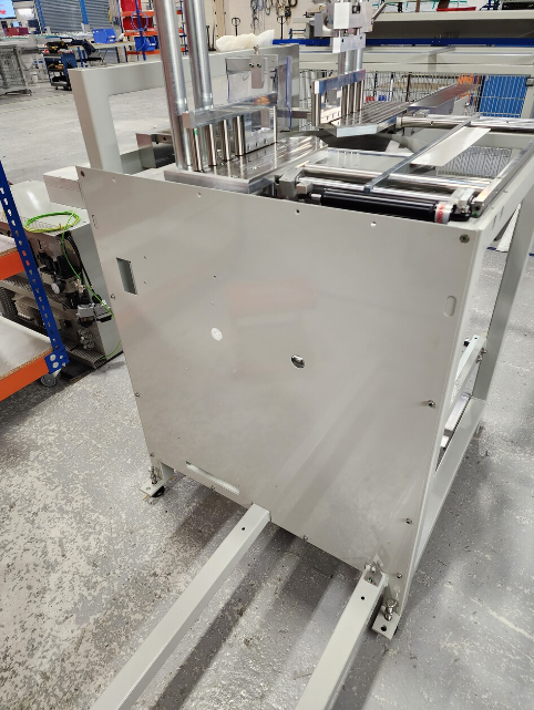
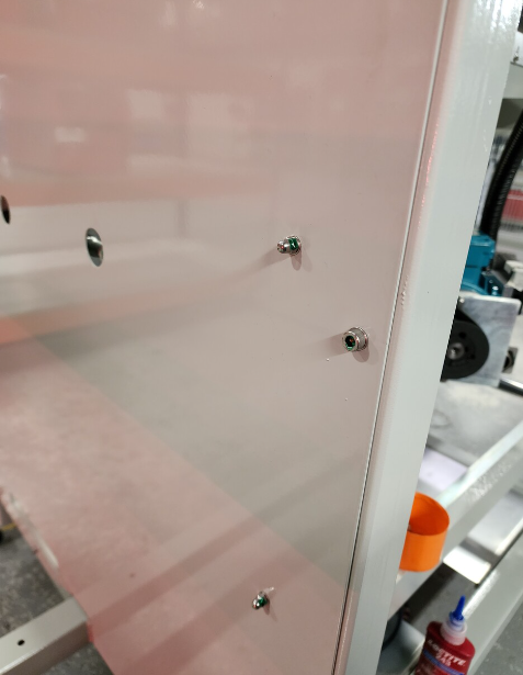
Étape 6 - Fit side sheet
Fit D0004391E Left hand side sheet
Use M6 x 12 socket caps and M6 A form washers
Use 2 off M6 x 10 Counter sunk for top 2 fixing points
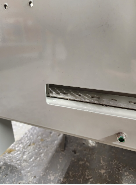
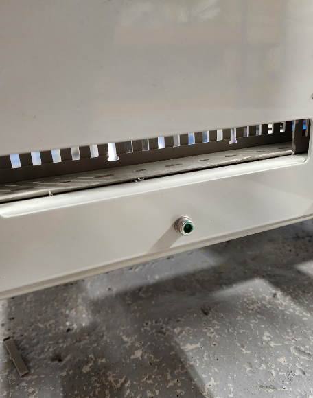
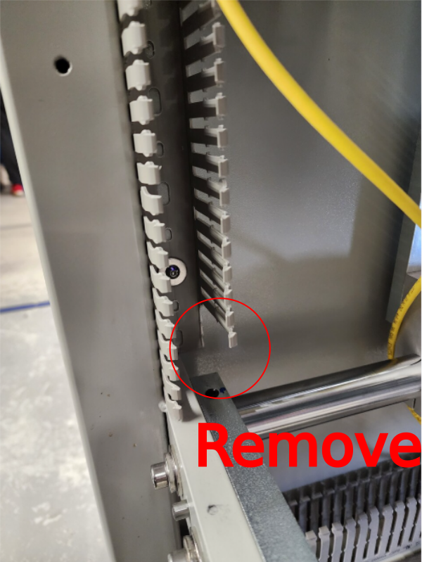
Étape 7 - Fit trunking to side sheet
Mark and drill pre cut trunking to fit as shown . Fix with
M5 x 10 button sockets, penny washers and back off with M5 A forms and dome nuts
Remove 3 off trunking tangs as shown for cable routing
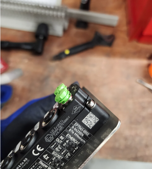
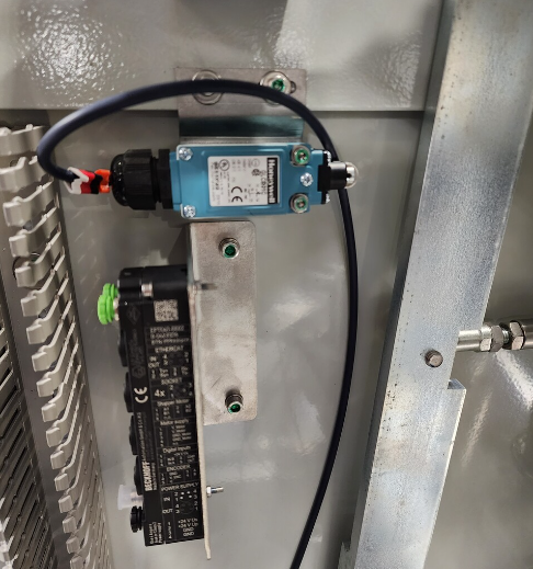
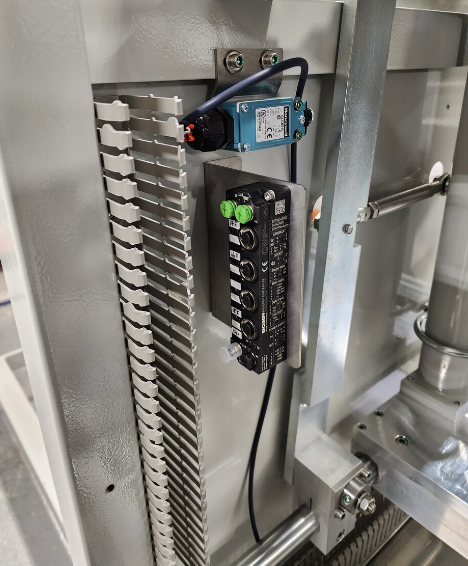
Étape 8 - Fit ethercat mount plate
Fit ethercat box to mounting plate using M3 x 25 socket caps , M3 A form washers and M3 nuts
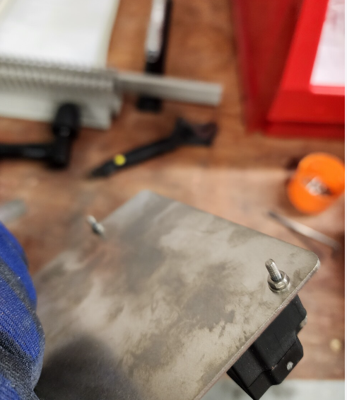
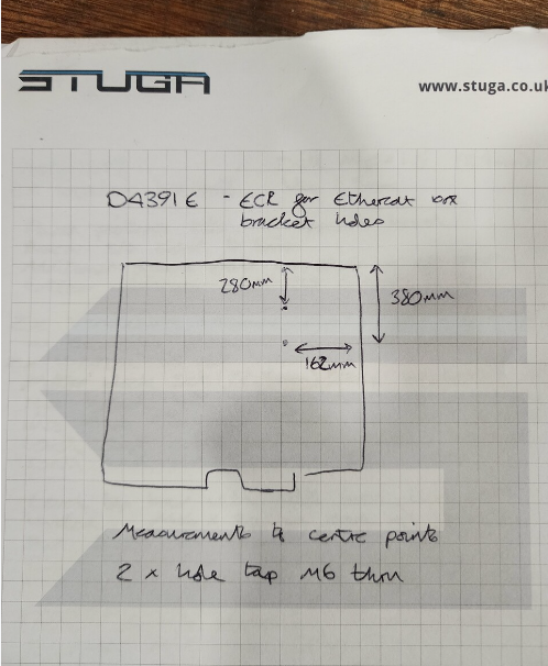
Fit ethercat mounting plate to side sheet at position shown , holes will require drilling to suit. Use M6 x 12 socket caps and penny washers, and back off with M6 A form washers and Dome nuts
ECR generated to add holes to side sheet for fixing 18/12/23
Use attached drawing to add holes until ECR processed
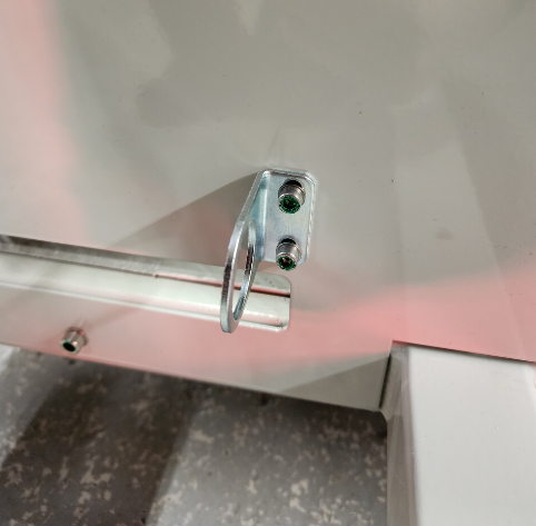
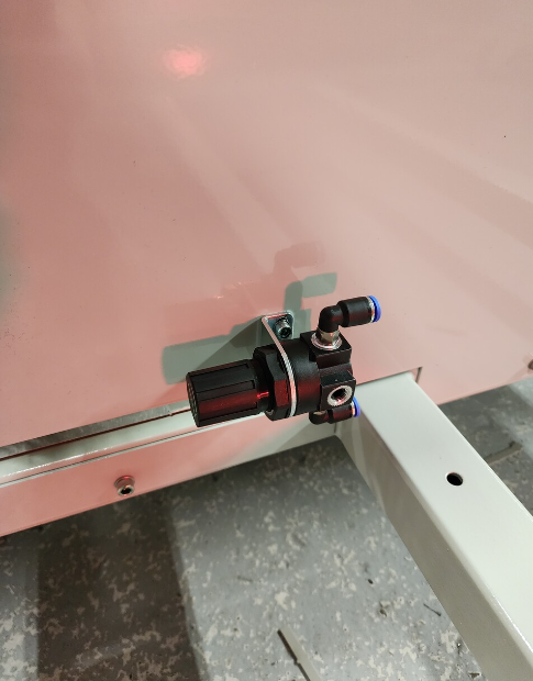
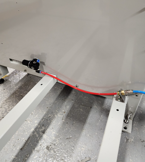
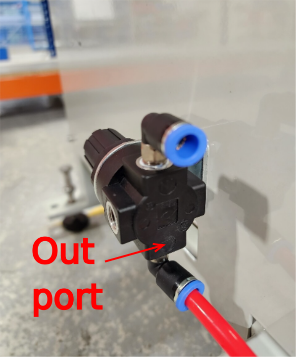
Étape 9 - Fit Regulator bracket
Fit regulator bracket to side sheet using 2 off M5 x 12 socket caps and A form washers
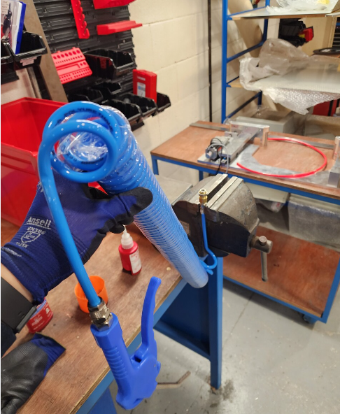
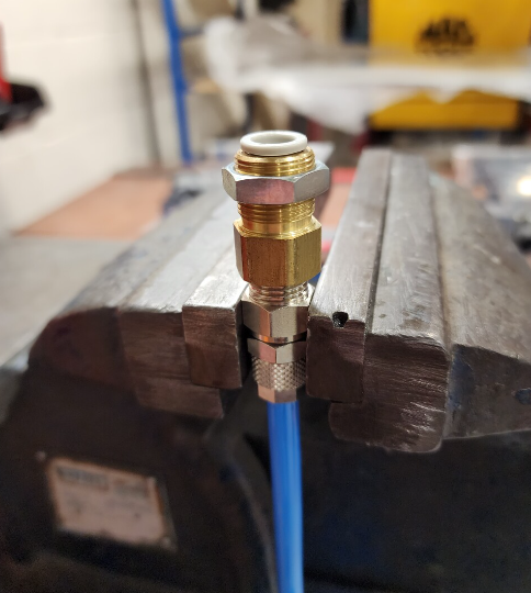
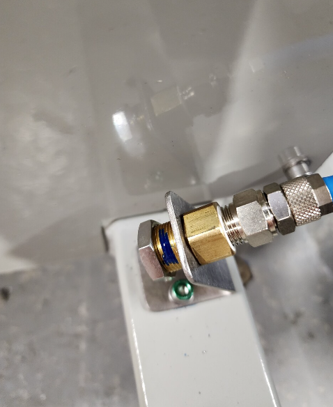
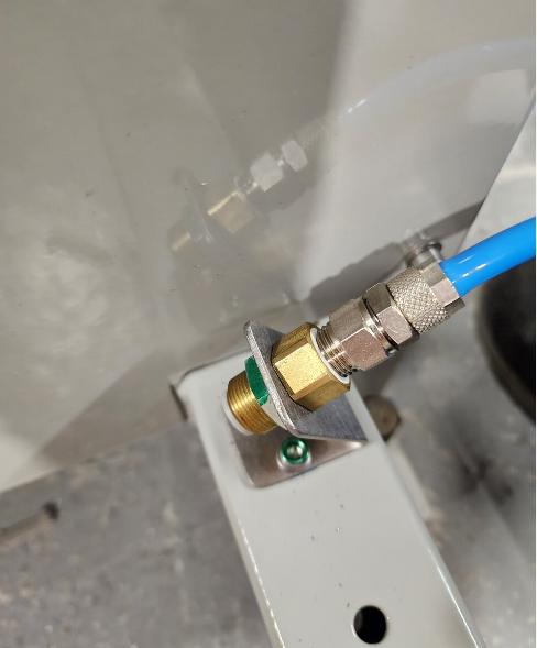
Étape 11 - Assemble air gun assembly
Assemble air gun assembly to bulk head fitting and fit to air gun bracket
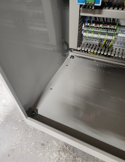
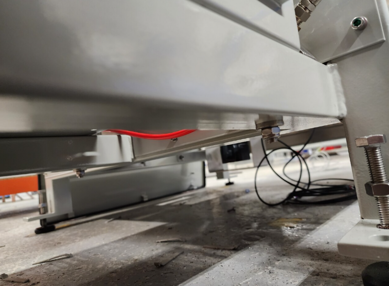
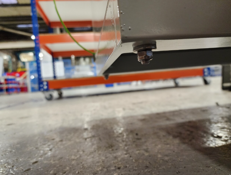
Étape 14 - Fix cabinet
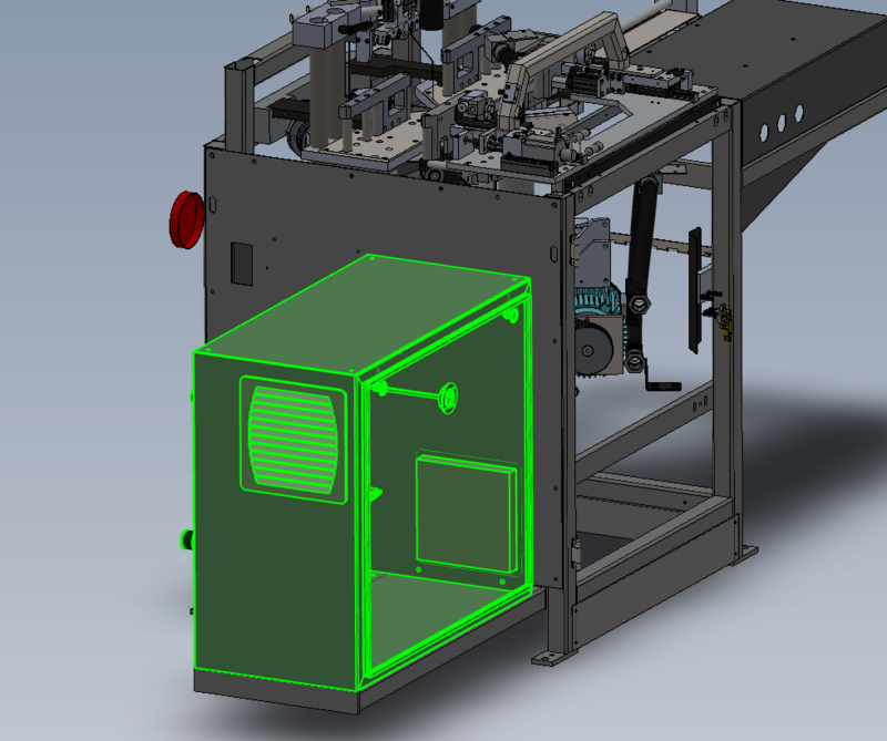
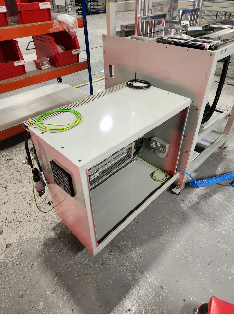
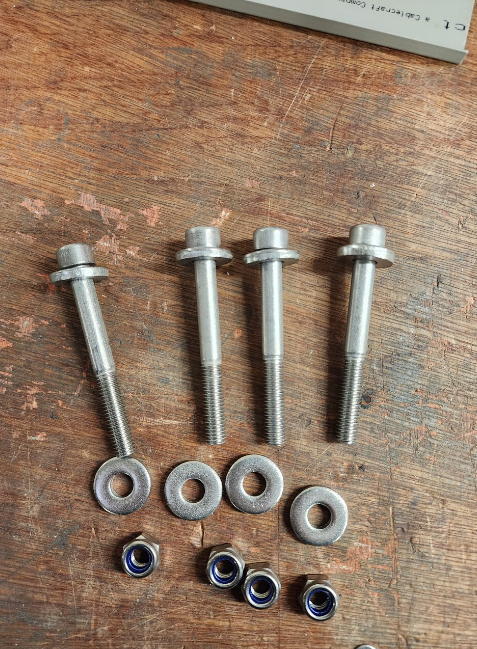
Fix cabinet to frame using M8 x 70 socket caps, heavy M8 washers and nyloc nuts
Draft

 Français
 English
 Deutsch
 Español
 Italiano
 Português