| [version en cours de rédaction] | [version en cours de rédaction] |
(Page créée avec « {{Tuto Details |Description=<translate>Designed to show how to install the 8 segments which make up the protection ring for the seal.</translate> |Difficulty=Easy |Duratio... ») |
m (Gareth Green a déplacé la page Autoflow R Axis Ring Seal Protection vers R0019228 Autoflow R Axis Ring Seal Protection : Add Assembly number) |
||
| (Une révision intermédiaire par le même utilisateur non affichée) | |||
| Ligne 1 : | Ligne 1 : | ||
{{Tuto Details | {{Tuto Details | ||
| + | |Main_Picture=Autoflow_R_Axis_Ring_Seal_Protection_20240131_161859.jpg | ||
|Description=<translate>Designed to show how to install the 8 segments which make up the protection ring for the seal.</translate> | |Description=<translate>Designed to show how to install the 8 segments which make up the protection ring for the seal.</translate> | ||
|Difficulty=Easy | |Difficulty=Easy | ||
| Ligne 77 : | Ligne 78 : | ||
{{Notes}} | {{Notes}} | ||
{{PageLang | {{PageLang | ||
| + | |Language=en | ||
|SourceLanguage=none | |SourceLanguage=none | ||
|IsTranslation=0 | |IsTranslation=0 | ||
| − | |||
}} | }} | ||
{{Tuto Status | {{Tuto Status | ||
|Complete=Draft | |Complete=Draft | ||
}} | }} | ||
Version actuelle datée du 19 novembre 2024 à 16:37
Designed to show how to install the 8 segments which make up the protection ring for the seal.
Introduction
Étape 1 - Clean down the area
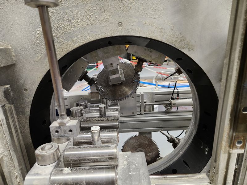
Using an air line and brush, clean away any and all swarf and other debris from the slewing ring.
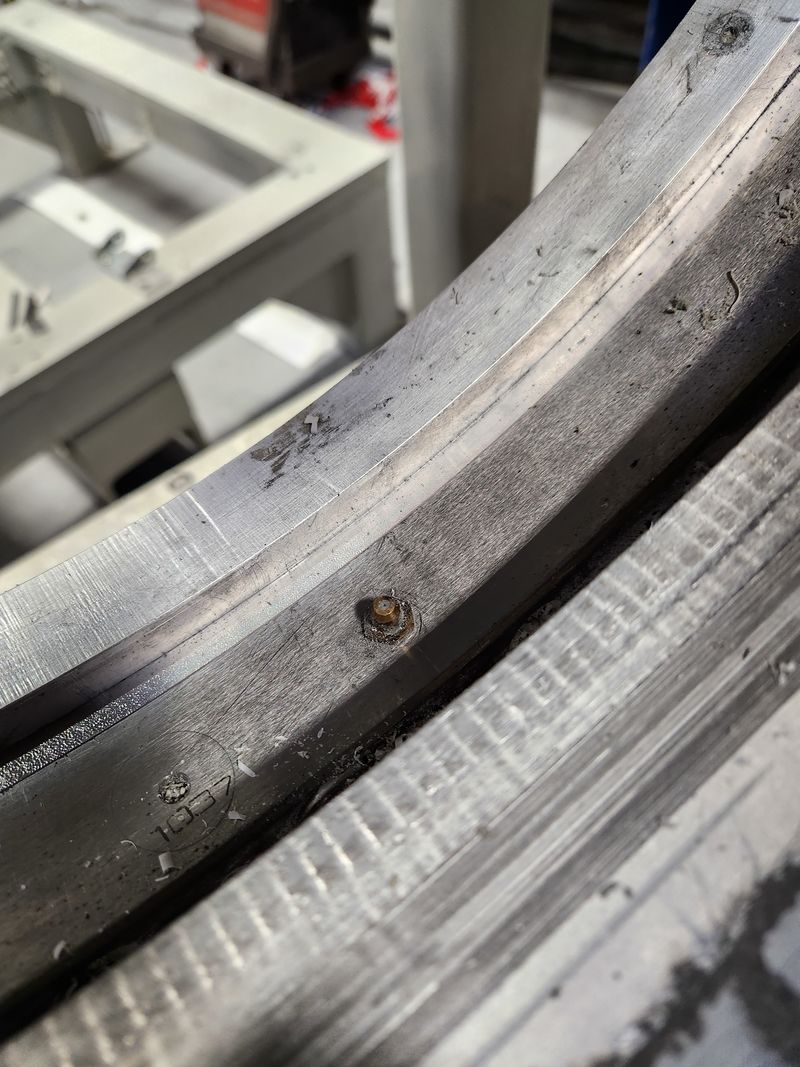
Next, using the rags and the FE10 solvent, wipe down the mating faces on the inside radius of the rear plate
Once clean, scuff the surface with the scotchbrite pad.
Wipe down the surface again with the solvent and rag.
Étape 2 - Position first segment
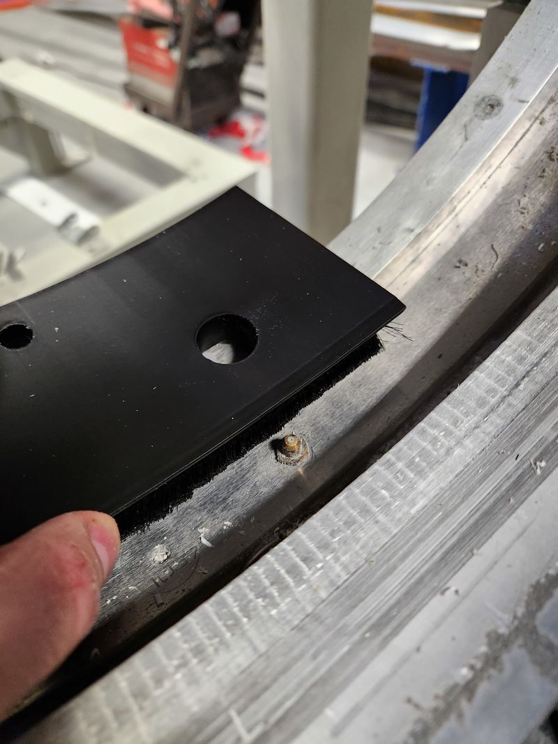
Ensure that the brush strip is installed in the segment.
Offer the segment into position, ensuring it sits on the mating faces.
Ensure the large diameter hole is sitting over the top of one of the grease nipples.
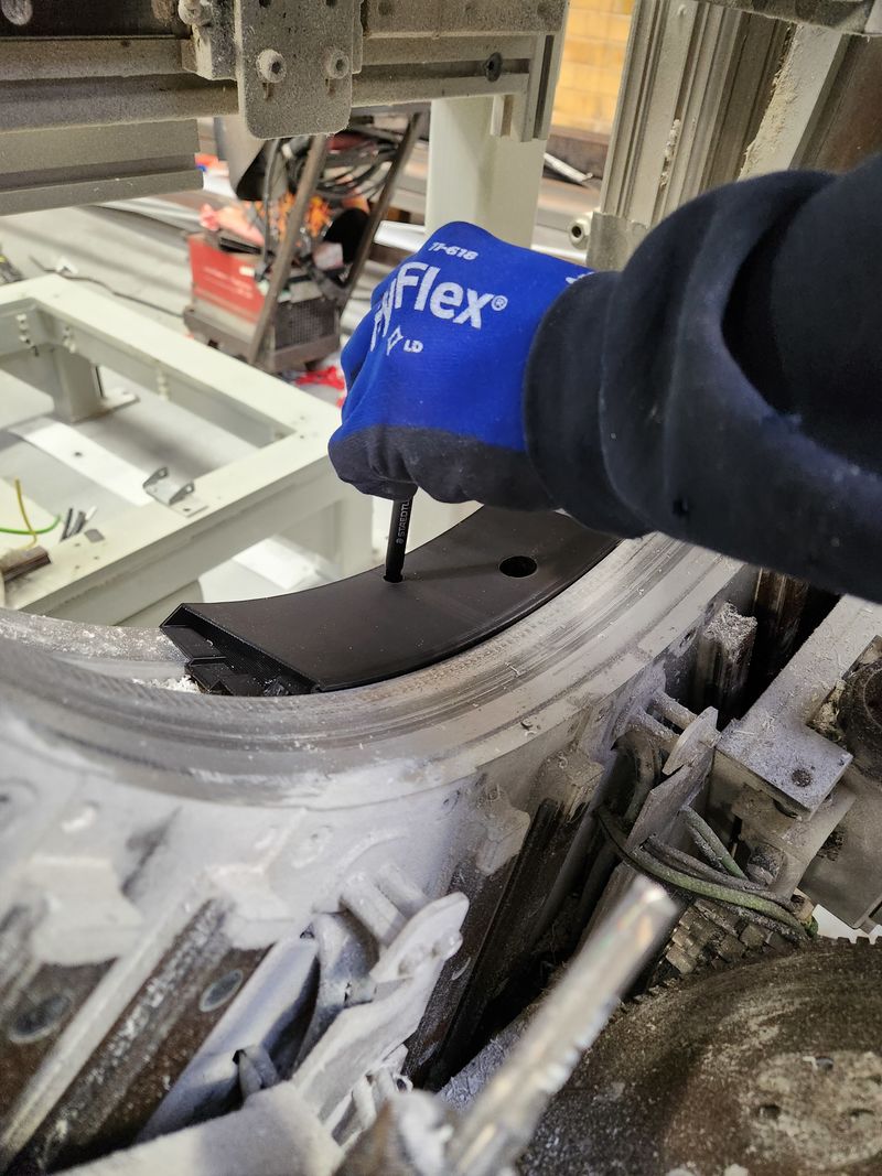
When in position, mark through the counterbored hole to mark the drill position on the back plate with a marker pen.
Remove the segment.
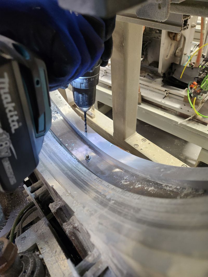
Drill and tap M5 at the marked position
Clean away any swarf, with the airline.
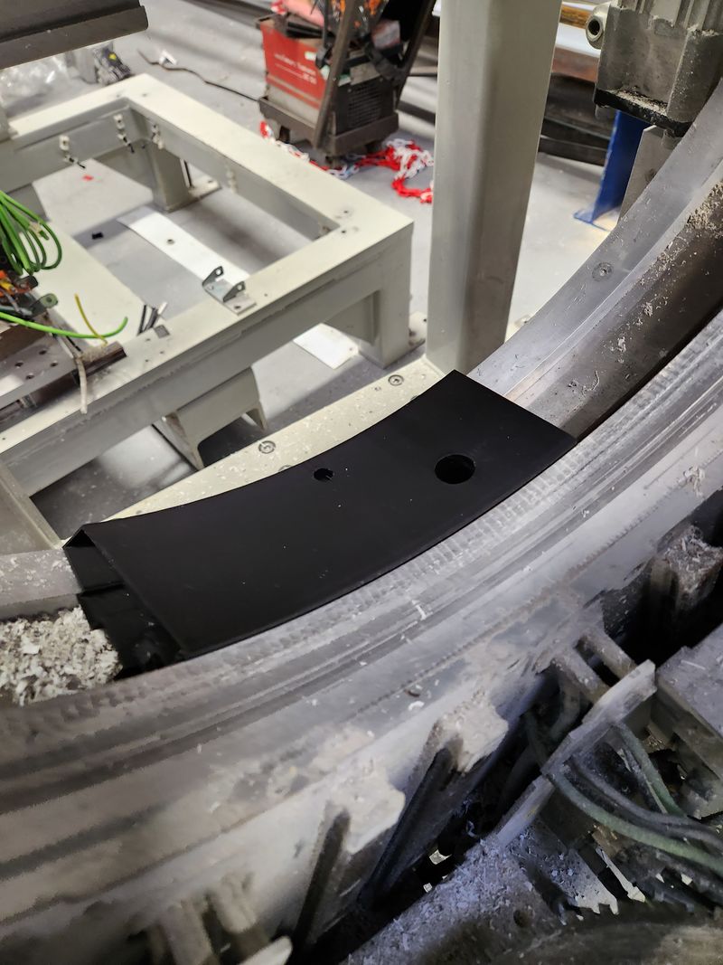
Add 3M tape to the inner radius face of the back plate. Ensuring the brush strip is in position, install the segment back into the same position and then secure using the M5 bolt and washer.
Install the cap to cover the grease nipple access hole.
Étape 3 - Install remaining segments
Repeat the process for the remaining segments.
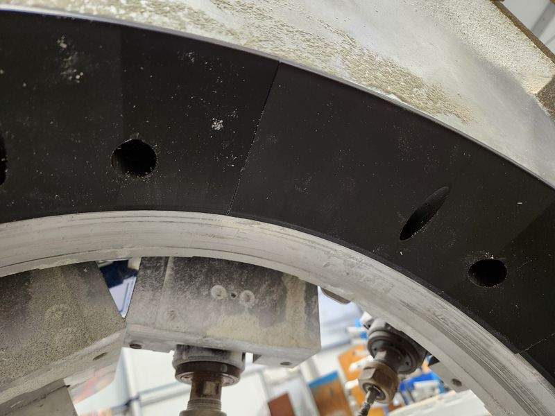
Note that the segments have tapered ends to allow each new segment to slot underneath the already fitted segments.
With each new segment being installed, it is critical to ensure that it butts up against the previous segment closely. This is so that when the last segment is installed, it has the required room to fit.
Étape 4 - Fit last segment
The last segment should fit exactly the same as the others. The tapered ends have been designed to allow it to fit under the fitted segments on the ring, and then drop down into its final correct position.
If, however, the last segment does not fit, provision has been made on one end of each segment to be “hollowed out” when printing, showing just the walls. This allows it to be filed or sanded back, to allow proper fitment.
Draft
 Français
 English
 Deutsch
 Español
 Italiano
 Português