| [version en cours de rédaction] | [version en cours de rédaction] |
| Ligne 213 : | Ligne 213 : | ||
Use 2 off M8 60 socket caps with M8 motor plate washers to fix</translate> | Use 2 off M8 60 socket caps with M8 motor plate washers to fix</translate> | ||
| + | |Step_Picture_00=R0000299_Stroke_assembly_rebuild_Part_2_2024-07-08_09-51-07.png | ||
| + | }} | ||
| + | {{Tuto Step | ||
| + | |Step_Title=<translate>Fit hard stop</translate> | ||
| + | |Step_Content=<translate>Refit D0007838 hardstop</translate> | ||
| + | |Step_Picture_00=R0000299_Stroke_assembly_rebuild_Part_2_2024-07-08_09-56-40.png | ||
| + | }} | ||
| + | {{Tuto Step | ||
| + | |Step_Title=<translate>Fit front flange</translate> | ||
| + | |Step_Content=<translate>Fit front flange</translate> | ||
}} | }} | ||
{{Notes}} | {{Notes}} | ||
Version du 8 juillet 2024 à 11:00
Instructions for correct assembly and setting of stroke assembly gearboxes Original part numbers R0000728 and R0000729

Difficulté
Très difficile
Durée
1 minute(s)
Sommaire
- 1 Introduction
- 2 Étape 1 - Unless otherwise stated
- 3 Étape 2 - Check components and fit
- 4 Étape 3 - Mount spindle assembly
- 5 Étape 4 - Check backlash
- 6 Étape 5 - Adjusting backlash
- 7 Étape 6 - Adjust Backlash
- 8 Étape 7 - Finalise spindle assembly
- 9 Étape 8 - Degrease mating faces and prepare
- 10 Étape 9 - Final assemble
- 11 Étape 10 - Quality Check
- 12 Étape 11 - Fit Shafts
- 13 Étape 12 - Fit damper bridge
- 14 Étape 13 - Fit hard stop
- 15 Étape 14 - Fit front flange
- 16 Commentaires
Introduction
The following instructions should be followed to ensure that correct assembly and setting are performed
Tools / consumables Required
Standard hex key set
Standard spanner set
Large adjustable spanner
Drifts and punches
Ballpein hammer
Soft hammer
FE10 Solvent
Hylomar Gasket
Parts Required
Kit R0000299 containing
B0000043 Double Angular bearing 15 I?D 35 O?D 15.9 long rubber seal 3 x 2
B0000105 Double Angular Bearing 15 I/D 35 O/D 15.9 Long x 1
B0000335 3ph Brake motor 2 pole 3000rpm x 1
B0000380 Double Angular Bearing 25 I/D 52 O/D 20.6 Long + rubber seal x 2
D0000059 Damper Bridge x 1
D0000062 Damper Bridge Boss x 2
D0007730 ZX4 V Notch Mk1 Spindle Shaft x1
D0007867 Bevel Gear (Left) x 1
D0007868 Bevel Gear (Right ) x 1
D0007873 Motor Gear x 1
D0007874 Pinion Gear x 1
D0007875 Pinion Shaft x 1Étape 1 - Unless otherwise stated
Always use Loctite 243 on all fasteners fitted unless stated different
All bearings should be an acceptable fit, with Loctite 641 and FE10 solvent used if required
All fasteners should be marked once finalised

Étape 2 - Check components and fit
Ensure that keyway B0000041 passes through bevel gear D0007867.
Fit key to shaft
Fit Pinion gear to shaft
Secure with M5x16 socket cap and D0007721 washer. Do not use adhesive at this point . Do not fit shims at this point


Étape 3 - Mount spindle assembly
Position spindle assembly to main gearbox body as shown.
Rotate spindle as shown to expose counterbored holes used for fixing
Fit 2 off M6x 30 socket caps and tension . Do not apply adhesive at this point

Étape 4 - Check backlash
Check backlash present by the following steps
1 Insert 4mm key into fastener shown and use to stop rotation of vertical shaft
2 Rock spindle clockwise and anti clockwise to gauge backlash present
Ideal backlash is 1mm movement in rotation of spindle (2)

Étape 5 - Adjusting backlash
Backlash can only be reduced, not increased. If no backlash is present when assembled with no shims, inform supervisor for correct route of action
To adjust backlash, shims can be used behind the bevel gear to move it closer to second bevel gear
As a general rule of thumb, the shims removed on stripdown of refurbished unit will be correct for rebuild. Work on this assumption but check when fitted that backlash setting is acceptable
Étape 6 - Adjust Backlash
1 Remove Bevel gear and key from assembly
2 Identify original shims fitted to gearbox
3 Fit shims to shaft
4 Refit bevel gear and parts to spindle
5 Refit assemble to main gearbox body and recheck backlash (step 4 )
6 Repeat 1-5 and Add additional shims if backlash is still to much


Étape 7 - Finalise spindle assembly
Once backlash has been set, spindle assembly must be finalised
Ensure all threads are degreased with FE10 solvent
Usel Loctite 243 on M5x 16 socket cap
Tension adequately , holding spindle as shown

Étape 8 - Degrease mating faces and prepare
Indicated faces should be degreased with FE10 solvent
Apply Hylomar as shown
Add remainder of M0000603 grease as shown


Étape 9 - Final assemble
Final fit spindle housing to main gearbox body
Use 4 off M6 x 30 socket caps with Loctite 243
Rotate spindle as shown to allow access to all fixing points
Smooth any excess hylomar with a clean rag

Étape 10 - Quality Check
Double check rotation is smooth and backlash is still correct after final fixings
Motor fitted is a braked variant, so rotation will have resistance, But should be smooth and consistent when rotated as shown
Report any discrepancies to supervisor
Étape 11 - Fit Shafts
Fit 2 off shafts H0007754 using 4 off M8x 20 kcp grubscrews with Loctite 243


Étape 12 - Fit damper bridge
Fit damper bridge D000000059, Spacers D0000062 and damper P0000165 as shown
Use 2 off M8 60 socket caps with M8 motor plate washers to fix

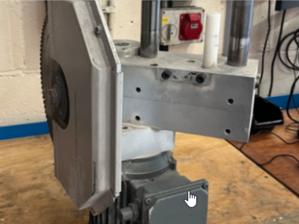
Étape 13 - Fit hard stop
Refit D0007838 hardstop

Étape 14 - Fit front flange
Fit front flange
Draft
 Français
 English
 Deutsch
 Español
 Italiano
 Português