| [en attente de relecture] | [en attente de relecture] |
| (3 révisions intermédiaires par le même utilisateur non affichées) | |||
| Ligne 1 : | Ligne 1 : | ||
{{Tuto Details | {{Tuto Details | ||
| + | |Main_Picture=ZX5_Transfer_Table_Setup_Correct_Pinion_Adjustment.jpg | ||
|Description=<translate>How to correctly set mesh between racks/pinions, V rail and delrin rollers</translate> | |Description=<translate>How to correctly set mesh between racks/pinions, V rail and delrin rollers</translate> | ||
|Difficulty=Easy | |Difficulty=Easy | ||
| Ligne 12 : | Ligne 13 : | ||
{{Tuto Step | {{Tuto Step | ||
|Step_Title=<translate>Misadjusted</translate> | |Step_Title=<translate>Misadjusted</translate> | ||
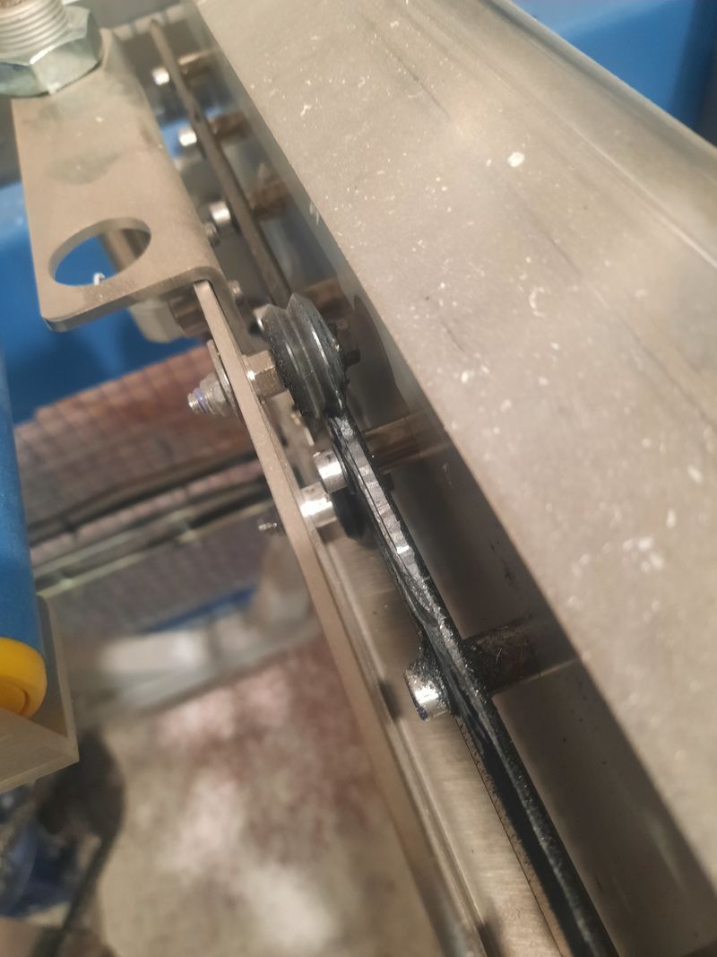
| − | |Step_Content=<translate></translate> | + | |Step_Content=<translate>Evidence of incorrect adjustment will be evidenced by components in the assemblies prematurely wearing and coming away from their fixings. |
| + | |||
| + | <br /></translate> | ||
|Step_Picture_00=ZX5_Transfer_Table_Setup_Damage_4.jpg | |Step_Picture_00=ZX5_Transfer_Table_Setup_Damage_4.jpg | ||
|Step_Picture_01=ZX5_Transfer_Table_Setup_Damage_3.jpg | |Step_Picture_01=ZX5_Transfer_Table_Setup_Damage_3.jpg | ||
| Ligne 19 : | Ligne 22 : | ||
|Step_Picture_02_annotation={"version":"2.4.6","objects":[{"type":"image","version":"2.4.6","originX":"left","originY":"top","left":-4,"top":-59,"width":2576,"height":1932,"fill":"rgb(0,0,0)","stroke":null,"strokeWidth":0,"strokeDashArray":null,"strokeLineCap":"butt","strokeDashOffset":0,"strokeLineJoin":"miter","strokeMiterLimit":4,"scaleX":0.26,"scaleY":0.26,"angle":0,"flipX":false,"flipY":false,"opacity":1,"shadow":null,"visible":true,"clipTo":null,"backgroundColor":"","fillRule":"nonzero","paintFirst":"fill","globalCompositeOperation":"source-over","transformMatrix":null,"skewX":0,"skewY":0,"crossOrigin":"","cropX":0,"cropY":0,"src":"https://stuga.dokit.app/images/2/29/ZX5_Transfer_Table_Setup_Damage_2.jpg","filters":[]}],"height":450.22288261515604,"width":600} | |Step_Picture_02_annotation={"version":"2.4.6","objects":[{"type":"image","version":"2.4.6","originX":"left","originY":"top","left":-4,"top":-59,"width":2576,"height":1932,"fill":"rgb(0,0,0)","stroke":null,"strokeWidth":0,"strokeDashArray":null,"strokeLineCap":"butt","strokeDashOffset":0,"strokeLineJoin":"miter","strokeMiterLimit":4,"scaleX":0.26,"scaleY":0.26,"angle":0,"flipX":false,"flipY":false,"opacity":1,"shadow":null,"visible":true,"clipTo":null,"backgroundColor":"","fillRule":"nonzero","paintFirst":"fill","globalCompositeOperation":"source-over","transformMatrix":null,"skewX":0,"skewY":0,"crossOrigin":"","cropX":0,"cropY":0,"src":"https://stuga.dokit.app/images/2/29/ZX5_Transfer_Table_Setup_Damage_2.jpg","filters":[]}],"height":450.22288261515604,"width":600} | ||
|Step_Picture_03=ZX5_Transfer_Table_Setup_Damage_1.jpg | |Step_Picture_03=ZX5_Transfer_Table_Setup_Damage_1.jpg | ||
| + | |Step_Picture_04=ZX5_Transfer_Table_Setup_No_rack_adjustment.jpg | ||
}} | }} | ||
{{Tuto Step | {{Tuto Step | ||
| Ligne 43 : | Ligne 47 : | ||
{{Tuto Step | {{Tuto Step | ||
|Step_Title=<translate>Adjust Rack to Pinion</translate> | |Step_Title=<translate>Adjust Rack to Pinion</translate> | ||
| − | |Step_Content=<translate>If there is no adjustment between the mounting plate and the rack as shown in the first picture, then we need to introduce some. | + | |Step_Content=<translate>If there is no adjustment between the mounting plate and the rack as shown in the first picture, then we need to introduce some. This is the most important step as it ensures all the parts are running parallel to eachother and not causing excessive force!!! |
| − | Get your sharpies oot and mark where the rack and pinion mate!!! Slacken off the larger screws, one at either end of the rack until you have a 3mm gap at each end. This is easy when removed, but once refitted you will need a cut down allen key to fit in the gap to adjust. Back off the set screws if not already. Slide the assembly back on and mesh the pinion to the rack at one | + | Get your sharpies oot and mark where the rack and pinion mate!!! Slacken off the larger screws, one at either end of the rack until you have a 3mm gap at each end. This is easy when removed, but once refitted you will need a cut down allen key to fit in the gap to adjust. Back off the set screws if not already. Slide the assembly back on and mesh the pinion to the rack at one of the ends, it does not matter which, lightly tighten a grubscrew on pinion to ensure there is no backlash felt between the key and keyway. Using a combination of the set screws and adjustment screw, adjust until there is no play between rack and pinion. Then turn each of the small set screws back an 1/8th to 1/4 turn and fully tighten the adjustment screw. This introduces a very small amount of play that should hardly be felt, but is just enough to stop premature wear between the two. Remove the pinion, slide the rack to the other end and repeat the process. Recheck the first end in case it has moved slightly while doing the second. Set distance from beam to popup cylinder using measurements from another assembly, or if you were clever enough you took these before taking everything apart? I wasn't! If it needs adjusted then slacken off the two setting bolts, they give around 10mm on the mounting slots. 1mm either way is good enough and will not cause problems. Reconnect air pipes, make sure everything is locked off and tight, job done.</translate> |
|Step_Picture_00=ZX5_Transfer_Table_Setup_No_rack_adjustment.jpg | |Step_Picture_00=ZX5_Transfer_Table_Setup_No_rack_adjustment.jpg | ||
|Step_Picture_01=ZX5_Transfer_Table_Setup_Correct_Pinion_Adjustment.jpg | |Step_Picture_01=ZX5_Transfer_Table_Setup_Correct_Pinion_Adjustment.jpg | ||
|Step_Picture_02=ZX5_Transfer_Table_Setup_Popup_Distance.jpg | |Step_Picture_02=ZX5_Transfer_Table_Setup_Popup_Distance.jpg | ||
| + | }} | ||
| + | {{Tuto Step | ||
| + | |Step_Title=<translate>End Stop</translate> | ||
| + | |Step_Content=<translate>Mechanical end stops should only ever be used as a fail safe in cases of sensors failing. These should be set so that the gears can never come off the racks. | ||
| + | |||
| + | <br /></translate> | ||
| + | |Step_Picture_00=ZX5_Transfer_Table_Crank_set_up_20201021_091143.jpg | ||
| + | |Step_Picture_00_annotation={"version":"2.4.6","objects":[{"type":"image","version":"2.4.6","originX":"left","originY":"top","left":0,"top":0,"width":4032,"height":3024,"fill":"rgb(0,0,0)","stroke":null,"strokeWidth":0,"strokeDashArray":null,"strokeLineCap":"butt","strokeDashOffset":0,"strokeLineJoin":"miter","strokeMiterLimit":4,"scaleX":0.15,"scaleY":0.15,"angle":0,"flipX":false,"flipY":false,"opacity":1,"shadow":null,"visible":true,"clipTo":null,"backgroundColor":"","fillRule":"nonzero","paintFirst":"fill","globalCompositeOperation":"source-over","transformMatrix":null,"skewX":0,"skewY":0,"crossOrigin":"","cropX":0,"cropY":0,"src":"https://stuga.dokit.app/images/c/cc/ZX5_Transfer_Table_Crank_set_up_20201021_091143.jpg","filters":[]},{"type":"wfarrow2line","version":"2.4.6","originX":"center","originY":"center","left":179,"top":216,"width":110,"height":104,"fill":"rgba(255,0,0,0)","stroke":"#FF0000","strokeWidth":4,"strokeDashArray":null,"strokeLineCap":"round","strokeDashOffset":0,"strokeLineJoin":"miter","strokeMiterLimit":4,"scaleX":1,"scaleY":1,"angle":0,"flipX":false,"flipY":false,"opacity":1,"shadow":null,"visible":true,"clipTo":null,"backgroundColor":"","fillRule":"nonzero","paintFirst":"fill","globalCompositeOperation":"source-over","transformMatrix":null,"skewX":0,"skewY":0,"x1":-55,"x2":55,"y1":52,"y2":-52,"x2a":45.963157969911876,"y2a":-32.446599116183584,"x2b":34.970975851442105,"y2b":-44.07294558764199},{"type":"wfarrow2circle","version":"2.4.6","originX":"center","originY":"center","left":124,"top":268,"width":16,"height":16,"fill":"#aaa","stroke":"#666","strokeWidth":0,"strokeDashArray":null,"strokeLineCap":"butt","strokeDashOffset":0,"strokeLineJoin":"miter","strokeMiterLimit":4,"scaleX":1,"scaleY":1,"angle":0,"flipX":false,"flipY":false,"opacity":0.5,"shadow":null,"visible":true,"clipTo":null,"backgroundColor":"","fillRule":"nonzero","paintFirst":"fill","globalCompositeOperation":"source-over","transformMatrix":null,"skewX":0,"skewY":0,"radius":8,"startAngle":0,"endAngle":6.283185307179586},{"type":"wfarrow2circle","version":"2.4.6","originX":"center","originY":"center","left":234,"top":164,"width":16,"height":16,"fill":"#aaa","stroke":"#666","strokeWidth":0,"strokeDashArray":null,"strokeLineCap":"butt","strokeDashOffset":0,"strokeLineJoin":"miter","strokeMiterLimit":4,"scaleX":1,"scaleY":1,"angle":0,"flipX":false,"flipY":false,"opacity":0.5,"shadow":null,"visible":true,"clipTo":null,"backgroundColor":"","fillRule":"nonzero","paintFirst":"fill","globalCompositeOperation":"source-over","transformMatrix":null,"skewX":0,"skewY":0,"radius":8,"startAngle":0,"endAngle":6.283185307179586}],"height":450,"width":600} | ||
| + | }} | ||
| + | {{Tuto Step | ||
| + | |Step_Title=<translate>Sensor Position</translate> | ||
| + | |Step_Content=<translate>Using a pair of 13mm spanners, nip the proximity sensors in place so that they are roughly in the middle of the slot. | ||
| + | |||
| + | {{Warning|...Ensure that the black part of the sensor is close enough to the rack that it makes the sensor but not so close that it is likely to get damaged by contact}} | ||
| + | |||
| + | Do this for all 6 sensors (2 on each assembly - 1 'home' and 1 'out') | ||
| + | |||
| + | {{Pin|...The 'Home' position for all cranks is when the pop ups are in the closest position to the machining centre - ready to receive the profile}}<br /></translate> | ||
| + | |Step_Picture_00=ZX5_Transfer_Table_Crank_set_up_20201021_091143.jpg | ||
| + | |Step_Picture_00_annotation={"version":"2.4.6","objects":[{"type":"image","version":"2.4.6","originX":"left","originY":"top","left":0,"top":0,"width":4032,"height":3024,"fill":"rgb(0,0,0)","stroke":null,"strokeWidth":0,"strokeDashArray":null,"strokeLineCap":"butt","strokeDashOffset":0,"strokeLineJoin":"miter","strokeMiterLimit":4,"scaleX":0.15,"scaleY":0.15,"angle":0,"flipX":false,"flipY":false,"opacity":1,"shadow":null,"visible":true,"clipTo":null,"backgroundColor":"","fillRule":"nonzero","paintFirst":"fill","globalCompositeOperation":"source-over","transformMatrix":null,"skewX":0,"skewY":0,"crossOrigin":"","cropX":0,"cropY":0,"src":"https://stuga.dokit.app/images/c/cc/ZX5_Transfer_Table_Crank_set_up_20201021_091143.jpg","filters":[]},{"type":"wfrect","version":"2.4.6","originX":"center","originY":"center","left":299.33,"top":270.52,"width":49.98,"height":227.35,"fill":"rgba(255,0,0,0)","stroke":"#FF0000","strokeWidth":2,"strokeDashArray":null,"strokeLineCap":"butt","strokeDashOffset":0,"strokeLineJoin":"miter","strokeMiterLimit":4,"scaleX":1,"scaleY":1,"angle":0,"flipX":false,"flipY":false,"opacity":1,"shadow":null,"visible":true,"clipTo":null,"backgroundColor":"","fillRule":"nonzero","paintFirst":"fill","globalCompositeOperation":"source-over","transformMatrix":null,"skewX":0,"skewY":0,"rx":0,"ry":0}],"height":450,"width":600} | ||
| + | }} | ||
| + | {{Tuto Step | ||
| + | |Step_Title=<translate>Clutch Tension</translate> | ||
| + | |Step_Content=<translate>Ensure the 3 clutches are tensioned correctly. | ||
| + | |||
| + | The purpose / goal of the clutch is to ensure that if a sensor fails, the motion of the rack is stopped safely on the end stop without damage or stress to the system | ||
| + | |||
| + | '''Too Tight''': | ||
| + | |||
| + | The clutch tension does not allow slippage causing the end stop to bend | ||
| + | |||
| + | |||
| + | '''Too Loose:''' | ||
| + | |||
| + | The clutch slips with a full table of profile</translate> | ||
| + | |Step_Picture_00=ZX5_Transfer_Table_Crank_set_up_Capture3.PNG | ||
| + | |Step_Picture_00_annotation={"version":"2.4.6","objects":[{"type":"image","version":"2.4.6","originX":"left","originY":"top","left":0,"top":0,"width":400,"height":530,"fill":"rgb(0,0,0)","stroke":null,"strokeWidth":0,"strokeDashArray":null,"strokeLineCap":"butt","strokeDashOffset":0,"strokeLineJoin":"miter","strokeMiterLimit":4,"scaleX":1.5,"scaleY":1.5,"angle":0,"flipX":false,"flipY":false,"opacity":1,"shadow":null,"visible":true,"clipTo":null,"backgroundColor":"","fillRule":"nonzero","paintFirst":"fill","globalCompositeOperation":"source-over","transformMatrix":null,"skewX":0,"skewY":0,"crossOrigin":"","cropX":0,"cropY":0,"src":"https://stuga.dokit.app/images/b/bd/ZX5_Transfer_Table_Crank_set_up_Capture3.PNG","filters":[]}],"height":795,"width":600} | ||
}} | }} | ||
{{Tuto Step | {{Tuto Step | ||
|Step_Title=<translate>Other Checks</translate> | |Step_Title=<translate>Other Checks</translate> | ||
| − | |Step_Content=<translate>If | + | |Step_Content=<translate>It is also worthwhile slackening off all the screws that hold the air pipe harness, let it find its own position and then tighten back up. If not done this can introduce pull on the brackets that carry the Delrin rollers.</translate> |
| + | }} | ||
| + | {{Tuto Step | ||
| + | |Step_Title=<translate>Testing</translate> | ||
| + | |Step_Content=<translate>The cranks can be run from the IO testing screen. The system will automatically stop the crank motor when the associated input is active, or after an adjustable timeout delay in the parameters. | ||
| + | |||
| + | |||
| + | '''Machining centre side:''' | ||
| + | |||
| + | Crank C - Machining centre offload | ||
| + | |||
| + | |||
| + | '''Sawing Side:''' | ||
| + | |||
| + | Crank D - Transfer Table | ||
| − | + | Crank E - Saw Preload</translate> | |
| + | |Step_Picture_00=ZX5_Transfer_Table_Crank_set_up_Capture.PNG | ||
| + | |Step_Picture_00_annotation={"version":"2.4.6","objects":[{"type":"image","version":"2.4.6","originX":"left","originY":"top","left":0,"top":0,"width":612,"height":341,"fill":"rgb(0,0,0)","stroke":null,"strokeWidth":0,"strokeDashArray":null,"strokeLineCap":"butt","strokeDashOffset":0,"strokeLineJoin":"miter","strokeMiterLimit":4,"scaleX":0.98,"scaleY":0.98,"angle":0,"flipX":false,"flipY":false,"opacity":1,"shadow":null,"visible":true,"clipTo":null,"backgroundColor":"","fillRule":"nonzero","paintFirst":"fill","globalCompositeOperation":"source-over","transformMatrix":null,"skewX":0,"skewY":0,"crossOrigin":"","cropX":0,"cropY":0,"src":"https://stuga.dokit.app/images/d/df/ZX5_Transfer_Table_Crank_set_up_Capture.PNG","filters":[]},{"type":"wfrect","version":"2.4.6","originX":"center","originY":"center","left":254.8,"top":174.78,"width":53.1,"height":35.12,"fill":"rgba(255,0,0,0)","stroke":"#0054FF","strokeWidth":2,"strokeDashArray":null,"strokeLineCap":"butt","strokeDashOffset":0,"strokeLineJoin":"miter","strokeMiterLimit":4,"scaleX":1,"scaleY":1,"angle":0,"flipX":false,"flipY":false,"opacity":1,"shadow":null,"visible":true,"clipTo":null,"backgroundColor":"","fillRule":"nonzero","paintFirst":"fill","globalCompositeOperation":"source-over","transformMatrix":null,"skewX":0,"skewY":0,"rx":0,"ry":0},{"type":"textbox","version":"2.4.6","originX":"center","originY":"center","left":197,"top":260,"width":117.85,"height":48.82,"fill":"#0054FF","stroke":"#0054FF","strokeWidth":1,"strokeDashArray":null,"strokeLineCap":"butt","strokeDashOffset":0,"strokeLineJoin":"miter","strokeMiterLimit":4,"scaleX":1,"scaleY":1,"angle":0,"flipX":false,"flipY":false,"opacity":1,"shadow":null,"visible":true,"clipTo":null,"backgroundColor":"","fillRule":"nonzero","paintFirst":"fill","globalCompositeOperation":"source-over","transformMatrix":null,"skewX":0,"skewY":0,"text":"Sensor Inputs","fontSize":20,"fontWeight":"normal","fontFamily":"sans-serif","fontStyle":"normal","lineHeight":1.16,"underline":false,"overline":false,"linethrough":false,"textAlign":"left","textBackgroundColor":"","charSpacing":0,"minWidth":20,"styles":{} },{"type":"wfrect","version":"2.4.6","originX":"center","originY":"center","left":491.61,"top":203.12,"width":56.31,"height":36.2,"fill":"rgba(255,0,0,0)","stroke":"#0054FF","strokeWidth":2,"strokeDashArray":null,"strokeLineCap":"butt","strokeDashOffset":0,"strokeLineJoin":"miter","strokeMiterLimit":4,"scaleX":1,"scaleY":1,"angle":0,"flipX":false,"flipY":false,"opacity":1,"shadow":null,"visible":true,"clipTo":null,"backgroundColor":"","fillRule":"nonzero","paintFirst":"fill","globalCompositeOperation":"source-over","transformMatrix":null,"skewX":0,"skewY":0,"rx":0,"ry":0},{"type":"textbox","version":"2.4.6","originX":"center","originY":"center","left":434,"top":264,"width":117.85,"height":48.82,"fill":"#0054FF","stroke":"#0054FF","strokeWidth":1,"strokeDashArray":null,"strokeLineCap":"butt","strokeDashOffset":0,"strokeLineJoin":"miter","strokeMiterLimit":4,"scaleX":1,"scaleY":1,"angle":0,"flipX":false,"flipY":false,"opacity":1,"shadow":null,"visible":true,"clipTo":null,"backgroundColor":"","fillRule":"nonzero","paintFirst":"fill","globalCompositeOperation":"source-over","transformMatrix":null,"skewX":0,"skewY":0,"text":"Sensor Outputs","fontSize":20,"fontWeight":"normal","fontFamily":"sans-serif","fontStyle":"normal","lineHeight":1.16,"underline":false,"overline":false,"linethrough":false,"textAlign":"left","textBackgroundColor":"","charSpacing":0,"minWidth":20,"styles":{} },{"type":"wfarrow2line","version":"2.4.6","originX":"center","originY":"center","left":211,"top":207,"width":48,"height":42,"fill":"rgba(255,0,0,0)","stroke":"#0054FF","strokeWidth":4,"strokeDashArray":null,"strokeLineCap":"round","strokeDashOffset":0,"strokeLineJoin":"miter","strokeMiterLimit":4,"scaleX":1,"scaleY":1,"angle":0,"flipX":false,"flipY":false,"opacity":1,"shadow":null,"visible":true,"clipTo":null,"backgroundColor":"","fillRule":"nonzero","paintFirst":"fill","globalCompositeOperation":"source-over","transformMatrix":null,"skewX":0,"skewY":0,"x1":-24,"x2":24,"y1":21,"y2":-21,"x2a":14.216502968810588,"y2a":-1.8092942849746168,"x2b":3.6804292429142995,"y2b":-13.850521400284663},{"type":"wfarrow2circle","version":"2.4.6","originX":"center","originY":"center","left":187,"top":228,"width":16,"height":16,"fill":"#aaa","stroke":"#666","strokeWidth":0,"strokeDashArray":null,"strokeLineCap":"butt","strokeDashOffset":0,"strokeLineJoin":"miter","strokeMiterLimit":4,"scaleX":1,"scaleY":1,"angle":0,"flipX":false,"flipY":false,"opacity":0.5,"shadow":null,"visible":true,"clipTo":null,"backgroundColor":"","fillRule":"nonzero","paintFirst":"fill","globalCompositeOperation":"source-over","transformMatrix":null,"skewX":0,"skewY":0,"radius":8,"startAngle":0,"endAngle":6.283185307179586},{"type":"wfarrow2circle","version":"2.4.6","originX":"center","originY":"center","left":235,"top":186,"width":16,"height":16,"fill":"#aaa","stroke":"#666","strokeWidth":0,"strokeDashArray":null,"strokeLineCap":"butt","strokeDashOffset":0,"strokeLineJoin":"miter","strokeMiterLimit":4,"scaleX":1,"scaleY":1,"angle":0,"flipX":false,"flipY":false,"opacity":0.5,"shadow":null,"visible":true,"clipTo":null,"backgroundColor":"","fillRule":"nonzero","paintFirst":"fill","globalCompositeOperation":"source-over","transformMatrix":null,"skewX":0,"skewY":0,"radius":8,"startAngle":0,"endAngle":6.283185307179586},{"type":"wfarrow2line","version":"2.4.6","originX":"center","originY":"center","left":449,"top":228.5,"width":32,"height":15,"fill":"rgba(255,0,0,0)","stroke":"#0054FF","strokeWidth":4,"strokeDashArray":null,"strokeLineCap":"round","strokeDashOffset":0,"strokeLineJoin":"miter","strokeMiterLimit":4,"scaleX":1,"scaleY":1,"angle":0,"flipX":false,"flipY":false,"opacity":1,"shadow":null,"visible":true,"clipTo":null,"backgroundColor":"","fillRule":"nonzero","paintFirst":"fill","globalCompositeOperation":"source-over","transformMatrix":null,"skewX":0,"skewY":0,"x1":-16,"x2":16,"y1":7.5,"y2":-7.5,"x2a":1.2862922906683885,"y2a":8.23234901228534,"x2b":-5.504649729023125,"y2b":-6.254993963056555},{"type":"wfarrow2circle","version":"2.4.6","originX":"center","originY":"center","left":433,"top":236,"width":16,"height":16,"fill":"#aaa","stroke":"#666","strokeWidth":0,"strokeDashArray":null,"strokeLineCap":"butt","strokeDashOffset":0,"strokeLineJoin":"miter","strokeMiterLimit":4,"scaleX":1,"scaleY":1,"angle":0,"flipX":false,"flipY":false,"opacity":0.5,"shadow":null,"visible":true,"clipTo":null,"backgroundColor":"","fillRule":"nonzero","paintFirst":"fill","globalCompositeOperation":"source-over","transformMatrix":null,"skewX":0,"skewY":0,"radius":8,"startAngle":0,"endAngle":6.283185307179586},{"type":"wfarrow2circle","version":"2.4.6","originX":"center","originY":"center","left":465,"top":221,"width":16,"height":16,"fill":"#aaa","stroke":"#666","strokeWidth":0,"strokeDashArray":null,"strokeLineCap":"butt","strokeDashOffset":0,"strokeLineJoin":"miter","strokeMiterLimit":4,"scaleX":1,"scaleY":1,"angle":0,"flipX":false,"flipY":false,"opacity":0.5,"shadow":null,"visible":true,"clipTo":null,"backgroundColor":"","fillRule":"nonzero","paintFirst":"fill","globalCompositeOperation":"source-over","transformMatrix":null,"skewX":0,"skewY":0,"radius":8,"startAngle":0,"endAngle":6.283185307179586}],"height":334,"width":600} | ||
}} | }} | ||
{{Notes}} | {{Notes}} | ||
| Ligne 63 : | Ligne 120 : | ||
}} | }} | ||
{{Tuto Status | {{Tuto Status | ||
| − | |Complete= | + | |Complete=Published |
}} | }} | ||
Version actuelle datée du 23 février 2024 à 10:50
How to correctly set mesh between racks/pinions, V rail and delrin rollers
Sommaire
Introduction
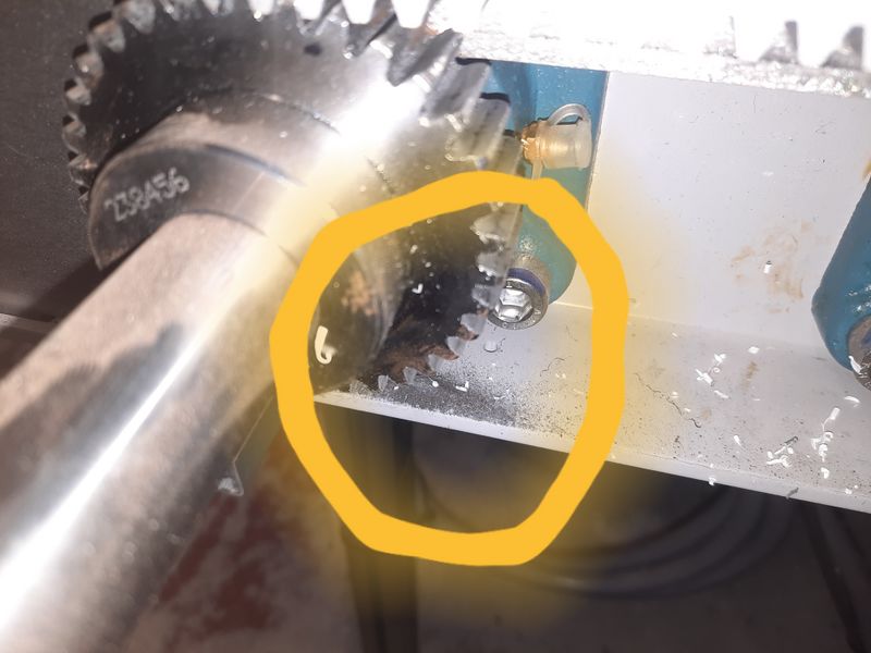
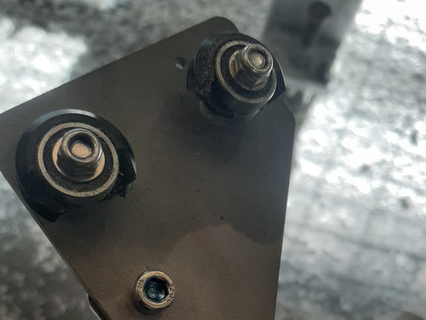
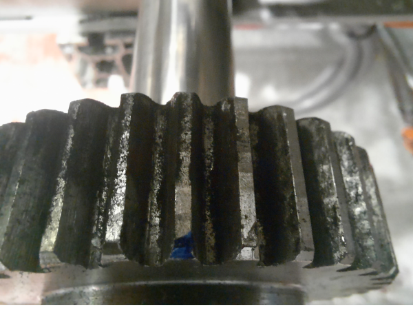
Étape 1 - Misadjusted
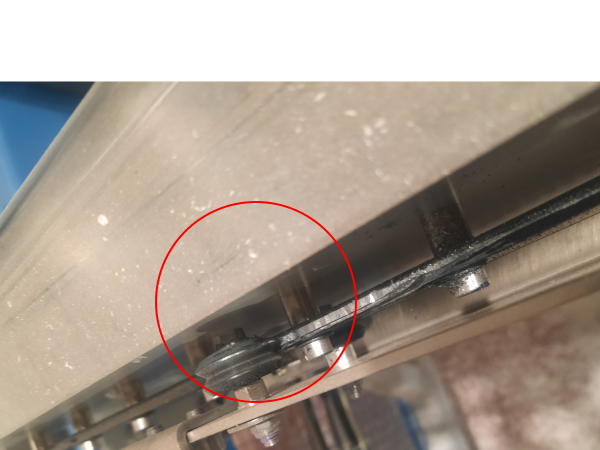
Evidence of incorrect adjustment will be evidenced by components in the assemblies prematurely wearing and coming away from their fixings.
Étape 2 - Access V rails and adjust.
Remove pinion gear by slackening off grubscrews and sliding away. Good idea to mark up original position.
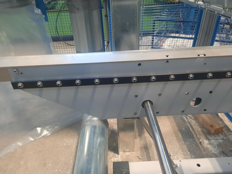
Disconnect airpipe feeding popup cylinder and slide off rack mounting plate.
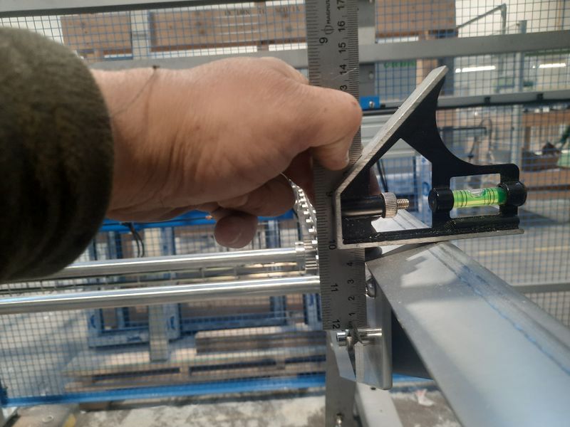
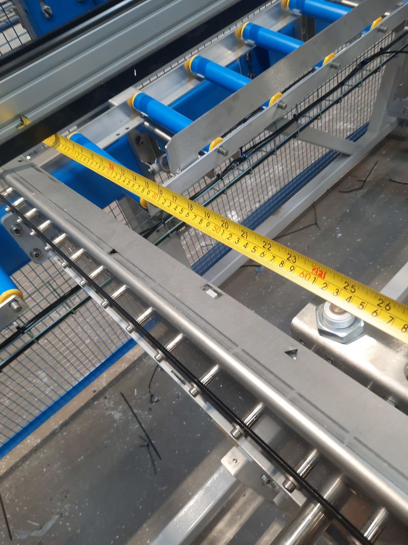
Slacken all 20 caphead screws, they only need a half to full turn. Move the rails up as far as they will go and then tighten just the screws on each end, finger tight is enough. These rails come in two parts, ensure they are fully mated together or they will cause tight spots later on. Using the joiners square in the picture set to 47mm, use it to set height of the V rails when the bubble shows it is level. Check at each end and in the middle. Once level, tighten all screws and recheck level.
Étape 3 - Check and adjust Delrin rollers
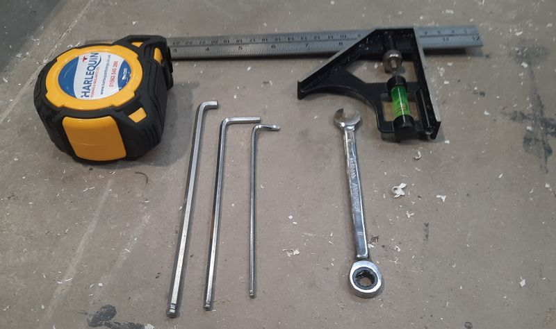
The rollers on top are mounted on eccentric bushes. We only need these just tight enough to not allow any slop or vertical play. Slacken the cams off completelely, you will need an 8mm spanner with the faces ground down to fit in the space.
Slide the plate onto the rail and tighten the eccentric bushes until any vertical play is removed. Lightly try to move the assembly on the X axis, if there is any slop then it needs to be a little tighter but probably no more than an 1/8th of a turn. Once set you should still be able to spin the rollers by hand, but still feel a fair bit of resistance. Once set slide the assembly over the full length of the V rails to check fo any tight spots. If there are then you need to check that the two halves of the fail are fully mated!!!
Étape 4 - Adjust Rack to Pinion
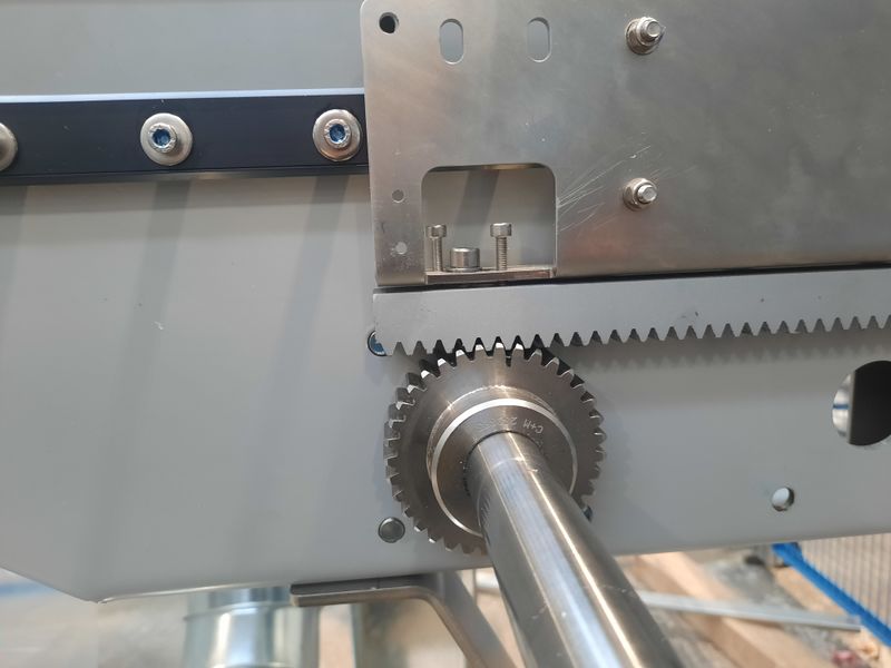
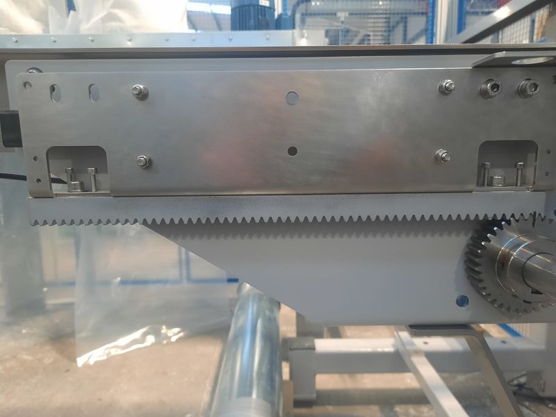
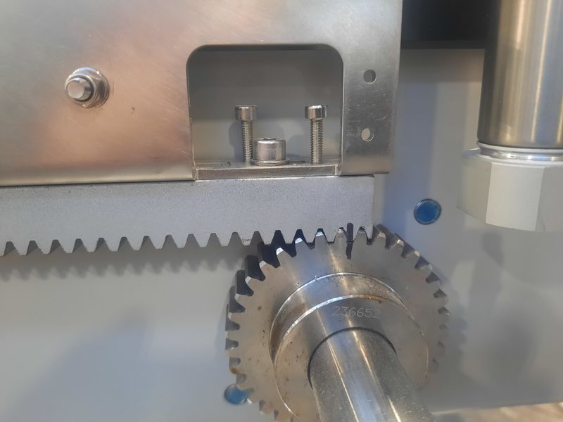
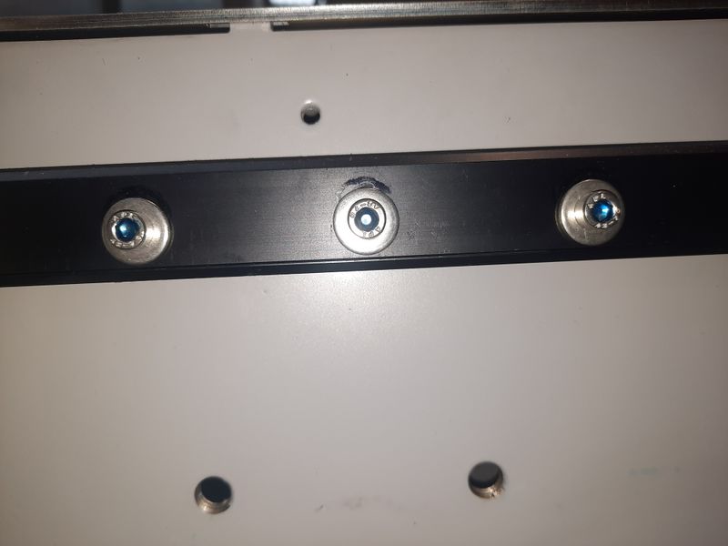
If there is no adjustment between the mounting plate and the rack as shown in the first picture, then we need to introduce some. This is the most important step as it ensures all the parts are running parallel to eachother and not causing excessive force!!!
Get your sharpies oot and mark where the rack and pinion mate!!! Slacken off the larger screws, one at either end of the rack until you have a 3mm gap at each end. This is easy when removed, but once refitted you will need a cut down allen key to fit in the gap to adjust. Back off the set screws if not already. Slide the assembly back on and mesh the pinion to the rack at one of the ends, it does not matter which, lightly tighten a grubscrew on pinion to ensure there is no backlash felt between the key and keyway. Using a combination of the set screws and adjustment screw, adjust until there is no play between rack and pinion. Then turn each of the small set screws back an 1/8th to 1/4 turn and fully tighten the adjustment screw. This introduces a very small amount of play that should hardly be felt, but is just enough to stop premature wear between the two. Remove the pinion, slide the rack to the other end and repeat the process. Recheck the first end in case it has moved slightly while doing the second. Set distance from beam to popup cylinder using measurements from another assembly, or if you were clever enough you took these before taking everything apart? I wasn't! If it needs adjusted then slacken off the two setting bolts, they give around 10mm on the mounting slots. 1mm either way is good enough and will not cause problems. Reconnect air pipes, make sure everything is locked off and tight, job done.
Étape 5 - End Stop
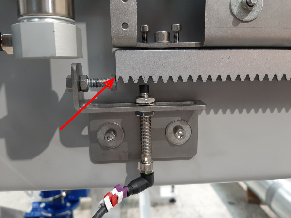
Mechanical end stops should only ever be used as a fail safe in cases of sensors failing. These should be set so that the gears can never come off the racks.
Étape 6 - Sensor Position
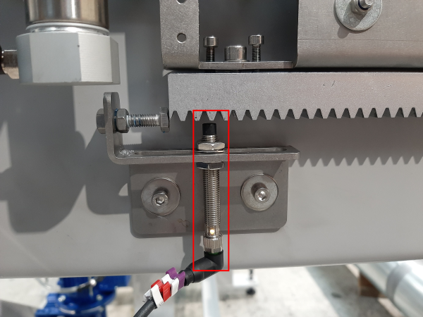
Using a pair of 13mm spanners, nip the proximity sensors in place so that they are roughly in the middle of the slot.
Do this for all 6 sensors (2 on each assembly - 1 'home' and 1 'out')
Étape 7 - Clutch Tension
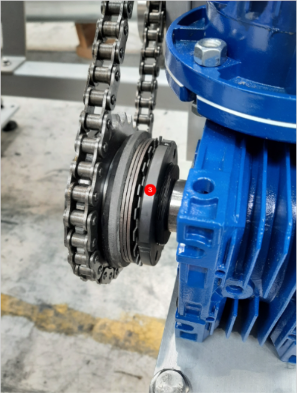
Ensure the 3 clutches are tensioned correctly.
The purpose / goal of the clutch is to ensure that if a sensor fails, the motion of the rack is stopped safely on the end stop without damage or stress to the system
Too Tight:
The clutch tension does not allow slippage causing the end stop to bend
Too Loose:
The clutch slips with a full table of profile
Étape 8 - Other Checks
It is also worthwhile slackening off all the screws that hold the air pipe harness, let it find its own position and then tighten back up. If not done this can introduce pull on the brackets that carry the Delrin rollers.
Étape 9 - Testing
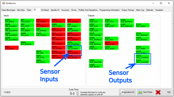
The cranks can be run from the IO testing screen. The system will automatically stop the crank motor when the associated input is active, or after an adjustable timeout delay in the parameters.
Machining centre side:
Crank C - Machining centre offload
Sawing Side:
Crank D - Transfer Table
Crank E - Saw Preload
Published
 Français
 English
 Deutsch
 Español
 Italiano
 Português