| [version en cours de rédaction] | [version en cours de rédaction] |
| (Une révision intermédiaire par le même utilisateur non affichée) | |||
| Ligne 15 : | Ligne 15 : | ||
External circlip pliers | External circlip pliers | ||
| + | |||
<u>'''Parts Required'''</u> | <u>'''Parts Required'''</u> | ||
| Ligne 44 : | Ligne 45 : | ||
{{Tuto Step | {{Tuto Step | ||
|Step_Title=<translate>Fit Y axis sleeve assembly</translate> | |Step_Title=<translate>Fit Y axis sleeve assembly</translate> | ||
| − | |Step_Content=<translate></translate> | + | |Step_Content=<translate>Insert pre built Y axis sleeve as shown</translate> |
| + | |Step_Picture_00=R0015315_Fit_Y_Axis_Drive_components_Screenshot_2023-11-01_133115.png | ||
| + | }} | ||
| + | {{Tuto Step | ||
| + | |Step_Title=<translate>Fit stepper housing block</translate> | ||
| + | |Step_Content=<translate>Fit Y axis stepper housing block as shown | ||
| + | |||
| + | |||
| + | Ensure block is mounted square and true | ||
| + | |||
| + | |||
| + | Pay attention to bearing fit | ||
| + | |||
| + | |||
| + | If bearing is loose, used solvent and bearing fit adhesive</translate> | ||
| + | |Step_Picture_00=R0015315_Fit_Y_Axis_Drive_components_Screenshot_2023-11-01_133041.png | ||
| + | }} | ||
| + | {{Tuto Step | ||
| + | |Step_Title=<translate>Position leadscrew</translate> | ||
| + | |Step_Content=<translate>Slide leadscrew into position shown</translate> | ||
| + | |Step_Picture_00=R0015315_Fit_Y_Axis_Drive_components_Screenshot_2023-11-01_133017.png | ||
| + | }} | ||
| + | {{Tuto Step | ||
| + | |Step_Title=<translate>Fit bearings</translate> | ||
| + | |Step_Content=<translate>Fit 2 off bearings and captivate with circlip</translate> | ||
| + | |Step_Picture_00=R0015315_Fit_Y_Axis_Drive_components_Screenshot_2023-11-01_133720.png | ||
| + | }} | ||
| + | {{Tuto Step | ||
| + | |Step_Title=<translate>Final leadscrew position</translate> | ||
| + | |Step_Content=<translate>Slide leadscrew into final position | ||
| + | |||
| + | |||
| + | Add M8 x 12 kcp grubscrews to secure leadscrew to sleeve</translate> | ||
| + | |Step_Picture_00=R0015315_Fit_Y_Axis_Drive_components_Screenshot_2023-11-01_133842.png | ||
| + | }} | ||
| + | {{Tuto Step | ||
| + | |Step_Title=<translate>Temporary fix leadscrew nut</translate> | ||
| + | |Step_Content=<translate>Temporarily fix position of leadscrew nut using 4 off M6 socket caps and a form washers</translate> | ||
| + | |Step_Picture_00=R0015315_Fit_Y_Axis_Drive_components_Screenshot_2023-11-01_133950.png | ||
| + | }} | ||
| + | {{Tuto Step | ||
| + | |Step_Title=<translate>Check movement</translate> | ||
| + | |Step_Content=<translate>Check axis movement along entire length . | ||
| + | |||
| + | |||
| + | Movement should be free and consistent</translate> | ||
| + | |Step_Picture_00=R0000711_Rotary_Base_Assembly_quality-assurance-testing.png | ||
| + | }} | ||
| + | {{Tuto Step | ||
| + | |Step_Title=<translate>Fit servo adapter block</translate> | ||
| + | |Step_Content=<translate>Dry fit servo adapter block | ||
| + | |||
| + | |||
| + | do not add final tension to this block</translate> | ||
| + | |Step_Picture_00=R0015315_Fit_Y_Axis_Drive_components_Screenshot_2023-11-01_133034.png | ||
| + | }} | ||
| + | {{Tuto Step | ||
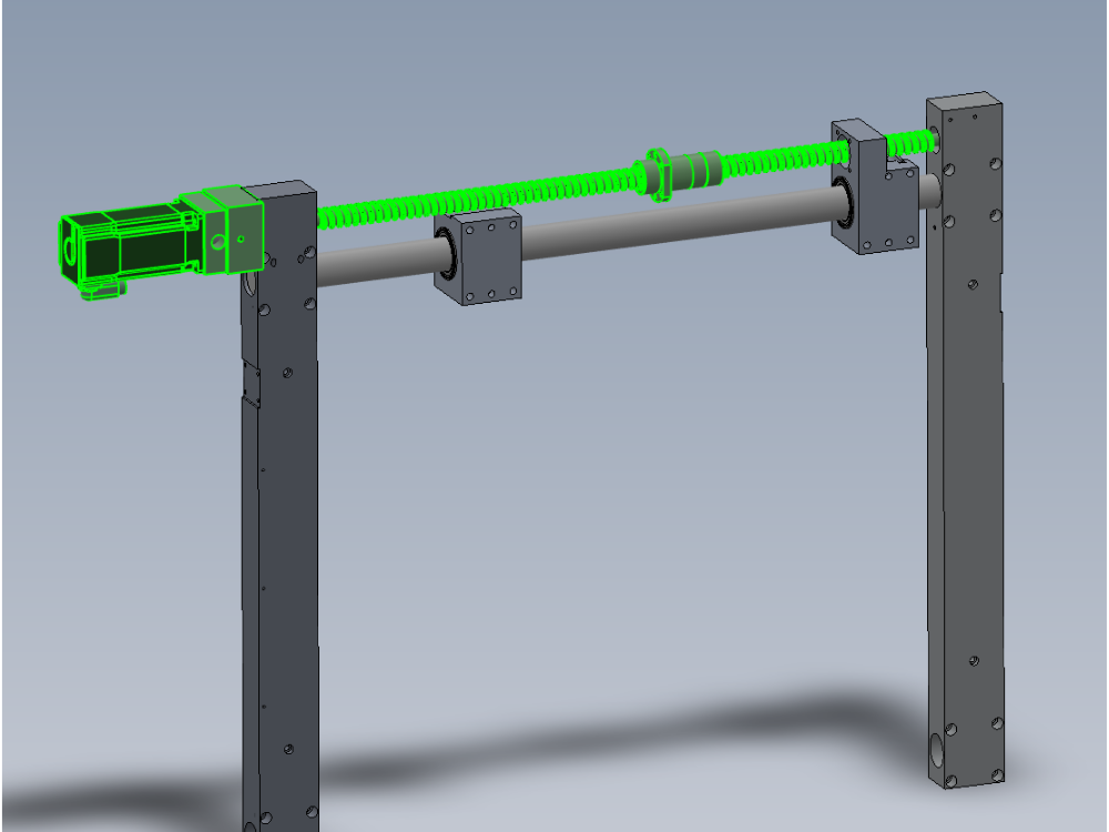
| + | |Step_Title=<translate>Fit servo motor</translate> | ||
| + | |Step_Content=<translate>Fit servo motor to adapter block | ||
| + | |||
| + | |||
| + | Servo should fit easily into servo adapter block | ||
| + | |||
| + | |||
| + | ~Adjust position of adapter block if fit is not correct</translate> | ||
| + | |Step_Picture_00=R0015315_Fit_Y_Axis_Drive_components_Screenshot_2023-11-01_132900.png | ||
| + | }} | ||
| + | {{Tuto Step | ||
| + | |Step_Title=<translate>Finalise servo adapter block</translate> | ||
| + | |Step_Content=<translate>Remove servo motor and finalise fasteners on servo adapter block</translate> | ||
| + | |Step_Picture_00=R0015315_Fit_Y_Axis_Drive_components_Screenshot_2023-11-01_133034.png | ||
| + | }} | ||
| + | {{Tuto Step | ||
| + | |Step_Title=<translate>Re fit servo motor</translate> | ||
| + | |Step_Content=<translate>Ensure motor is orientated correctly , servo plug facing down | ||
| + | |||
| + | |||
| + | Finalise socket caps fixing motor to adapter block</translate> | ||
| + | |Step_Picture_00=R0015315_Fit_Y_Axis_Drive_components_Screenshot_2023-11-01_132900.png | ||
| + | }} | ||
| + | {{Tuto Step | ||
| + | |Step_Title=<translate>Fit keyway locking grubscrew</translate> | ||
| + | |Step_Content=<translate>Fit locking grubscrew accessed through indicated hole</translate> | ||
| + | |Step_Picture_00=R0015315_Fit_Y_Axis_Drive_components_Screenshot_2023-11-01_134621.png | ||
| + | }} | ||
| + | {{Tuto Step | ||
| + | |Step_Title=<translate>Check movement</translate> | ||
| + | |Step_Content=<translate>Check Axis movement again. There should be no change in consistency of movement or force required | ||
| + | |||
| + | |||
| + | If changes are evident , investigate !</translate> | ||
| + | |Step_Picture_00=Zx5_Module_C_and_E_support_arm_alignment_quality-assurance-testing.png | ||
| + | }} | ||
| + | {{Tuto Step | ||
| + | |Step_Title=<translate>Remove leadscrew nut fixing</translate> | ||
| + | |Step_Content=<translate>Remove 4 off fasteners attaching leadscrew nut to bearing block | ||
| + | |||
| + | |||
| + | This is required for rotary ring installation at a later stage</translate> | ||
| + | |Step_Picture_00=R0015315_Fit_Y_Axis_Drive_components_Screenshot_2023-11-01_133950.png | ||
}} | }} | ||
{{Notes}} | {{Notes}} | ||
Version actuelle datée du 1 novembre 2023 à 16:33
Fitting instructions for Y Axis drive

Difficulté
Moyen
Durée
0.5 heure(s)
Sommaire
- 1 Introduction
- 2 Étape 1 - Unless otherwise stated
- 3 Étape 2 - Fit Y axis sleeve assembly
- 4 Étape 3 - Fit stepper housing block
- 5 Étape 4 - Position leadscrew
- 6 Étape 5 - Fit bearings
- 7 Étape 6 - Final leadscrew position
- 8 Étape 7 - Temporary fix leadscrew nut
- 9 Étape 8 - Check movement
- 10 Étape 9 - Fit servo adapter block
- 11 Étape 10 - Fit servo motor
- 12 Étape 11 - Finalise servo adapter block
- 13 Étape 12 - Re fit servo motor
- 14 Étape 13 - Fit keyway locking grubscrew
- 15 Étape 14 - Check movement
- 16 Étape 15 - Remove leadscrew nut fixing
- 17 Commentaires
Introduction
Tools Required
Standard hex key set
External circlip pliers
Parts Required
B0000344 Circlip 15mm External x 1
D0001927 Intermediate Housing (AM3032) x 1
D0006487 Y Stepper Housing x 1
R0000962E Bench assemble Y axis Components
Étape 1 - Unless otherwise stated
Use Loctite 243 on all fasteners
Use Loctite 572 on all threaded pneumatic connection
Pen mark all fasteners to show finalised

Étape 2 - Fit Y axis sleeve assembly
Insert pre built Y axis sleeve as shown

Étape 3 - Fit stepper housing block
Fit Y axis stepper housing block as shown
Ensure block is mounted square and true
Pay attention to bearing fit
If bearing is loose, used solvent and bearing fit adhesive

Étape 4 - Position leadscrew
Slide leadscrew into position shown

Étape 5 - Fit bearings
Fit 2 off bearings and captivate with circlip

Étape 6 - Final leadscrew position
Slide leadscrew into final position
Add M8 x 12 kcp grubscrews to secure leadscrew to sleeve

Étape 7 - Temporary fix leadscrew nut
Temporarily fix position of leadscrew nut using 4 off M6 socket caps and a form washers

Étape 8 - Check movement
Check axis movement along entire length .
Movement should be free and consistent

Étape 9 - Fit servo adapter block
Dry fit servo adapter block
do not add final tension to this block

Étape 10 - Fit servo motor
Fit servo motor to adapter block
Servo should fit easily into servo adapter block
~Adjust position of adapter block if fit is not correct

Étape 11 - Finalise servo adapter block
Remove servo motor and finalise fasteners on servo adapter block
Étape 12 - Re fit servo motor
Ensure motor is orientated correctly , servo plug facing down
Finalise socket caps fixing motor to adapter block
Étape 13 - Fit keyway locking grubscrew
Fit locking grubscrew accessed through indicated hole

Étape 14 - Check movement
Check Axis movement again. There should be no change in consistency of movement or force required
If changes are evident , investigate !

Étape 15 - Remove leadscrew nut fixing
Remove 4 off fasteners attaching leadscrew nut to bearing block
This is required for rotary ring installation at a later stage
Draft
 Français
 English
 Deutsch
 Español
 Italiano
 Português