| [version en cours de rédaction] | [version en cours de rédaction] |
m (Gareth Green a déplacé la page ZX5 Setup - Infeed Measure Sensor Calibration vers TB0445 ZX5 Setup - Infeed Measure Sensor Calibration : Added TB number) |
|||
| Ligne 1 : | Ligne 1 : | ||
{{Tuto Details | {{Tuto Details | ||
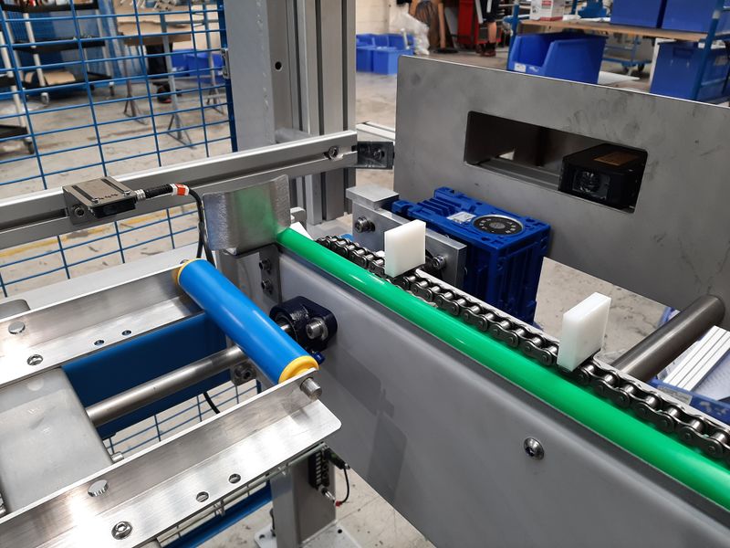
| + | |Main_Picture=TB0445_ZX5_Setup_-_Infeed_Measure_Sensor_Calibration_20201009_091335.jpg | ||
|Description=<translate>ZX5 Setup - Infeed Measure Sensor Calibration</translate> | |Description=<translate>ZX5 Setup - Infeed Measure Sensor Calibration</translate> | ||
|Categories=Maintenance | |Categories=Maintenance | ||
| Ligne 66 : | Ligne 67 : | ||
{{Notes}} | {{Notes}} | ||
{{PageLang | {{PageLang | ||
| + | |Language=en | ||
|SourceLanguage=none | |SourceLanguage=none | ||
|IsTranslation=0 | |IsTranslation=0 | ||
| − | |||
}} | }} | ||
{{Tuto Status | {{Tuto Status | ||
|Complete=Draft | |Complete=Draft | ||
}} | }} | ||
Version actuelle datée du 9 octobre 2020 à 10:21
ZX5 Setup - Infeed Measure Sensor Calibration
Introduction
The ZX5 has two bar measuring systems – the side laser and the sensor array.
The side laser scans the bar as it moves into the final loading location, which gives the software a “heads-up” for the length of the bar. If the length is different to expected, the software will then use the sensor array to measure the bar length.
There are 2 measurement methods because the side laser is not 100% reliable, especially on shorter lengths below 3000mm. However, it does mean the system does not have to grip and measure / reoptimize each bar length, so improves the cycle time.
The sequence is as follows
1. During the conveyor loading, measure the length using the side laser
2. Once loaded to backfence, check the backfence sensor array.
3. If the sensor array rough measurement does not match the laser –
a. If the laser measured length < infeedLaserRemeasure, continue and measure with rear sensors
b. If the laser measured length < infeedLaserRemeasure, flag an error that laser has not measured correctly.
c. If it does match, use the laser value to reoptimize the bar if it is different than expected
4. Load and Grip bar, if necessary, measure accurately with rear sensor arrayÉtape 1 - Side Laser
The laser should be aligned to ensure the beam is level up / down and parallel to the backfence. The path should follow the Yellow edge of the lift rollers on the infeed table.
Length feedback from the measurement system is visible all the time on the service form.
- Measure and mark the infeed table at fixed positions from the loading fence at MH end – (3m, 4m, 5m, 6m)
- Use a short offcut of profile with a label on the end to act a a fixed reflector at the marked positions – check against the feedback on the screen.
- Adjust the lengthMeasureOffset parameter to get the screen measurements to match reality (+/-10mm)
Étape 2 - Measure Array
Firstly, adjust the sensor dark / light and range correctly - see online video https://vimeo.com/294109652/c84d27e9f4
Note to experienced engineers: the version 6 software makes this a lot easier to set up than older software versions
- Using a tape rule from the MH end loading fence, note where the first sensor dot hits the tape
- Repeat for all 8 sensors
- Add these to the offcut sensor positions
- Run 3 different sizes of offcut through machine, noting the actual length, and the length measured by the machine. All the lengths should have a similar error
- Adjust the infeedToZeroX to get the machine measuring correctly (+5mm/-0mm). This parameter represents the distance from the loading fence to the zero datum
Draft

 Français
 English
 Deutsch
 Español
 Italiano
 Português